13EATON EP Control for Heavy Duty Series 2 Piston Pumps Parts & Service 08-10-0002-EN-0901 September 2001
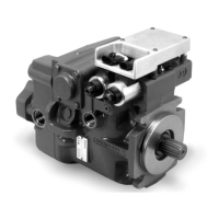
Step 22
Carefully position the electronic
module. Tuck all cables under the
module. Caution: Avoid pinching
cables at mounting points.
Install the three lockwashers and
three 10-24 button head cap
screws. Torque the three screws to
40-48 lbf·in.
Step 23
Power should still be disconnected
to the input device. Connect the
command input device to the three-
pin connector on the electronic
module.
Step 24
Connect the electrical power source
to the two-pin connector on the EP
Control electronic module. Install a
3 Amp SLO-BLO
®
fuse. Refer to the
Interconnect Schematic on page 13.
Recheck your work and then recon-
nect the power to the vehicle or
system.
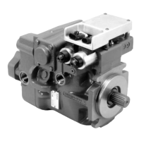
Step 25
The pump is now ready to return to
operation.
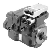
Step 21
Connect the EP Control electronic
module and the solenoid coils. The
four-pin connectors must be latched
securely.
Repair & Service
 Loading...