14 EATON EP Control for Heavy Duty Series 2 Piston Pumps Parts & Service 08-10-0002-EN-0901 September 2001
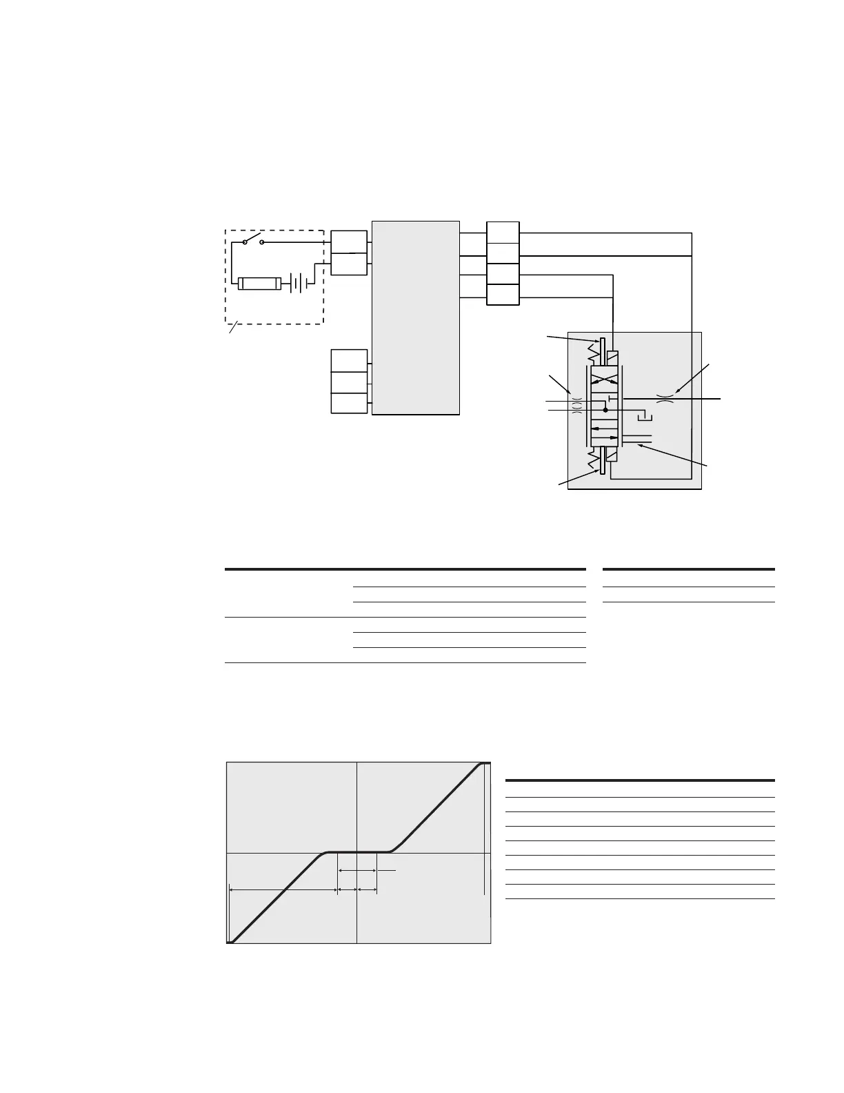
Interconnect
Schematic
A +
B -
POWER
SUPPLY
CONNECTOR
(2-Pin)
see chart
Customer
Supplied
Components
Valve
Assembly
Electronic
Module
Proportional
Solenoid 1
Solenoid
Connector
Proportional
Solenoid 2
S1
S2
P
Mechanical
Swashplate
Feedback
Supply Orifice
(Optional)
Servo Orifices
(Optional)
A
B
C
COMMAND
INPUT SIGNAL
CONNECTOR
(3-Pin)
see chart
Battery or
Power Supply
FUSE
On/Off Switch
+-
A
B
C
D
Power Supply Connector
PINS WIRE COLOR SIGNAL
A Red + Supply Voltage
B Black Supply Return
Fuse Rating
3 Amp SLO-BLO
®
(Time Delay) fuse for
12-24 Vdc system - customer supplied
Command Input Signal Connector
COMMAND INPUT SIGNAL PINS WIRE COLOR SIGNAL
A Black Ref Low - 1 Vdc
1 to 6 Vdc Potentiometric B Green Command (wiper)
C Red Ref Hi - 6 Vdc
A Orange Loop Return
±4-20 mA Current Loop B White Loop In
CNo Connection Required*
*EP Control Electronic Module Mating Connector Kit 990762-000 contains plug
used to seal mating end connector.
Pump Displacement
vs. Input Signal
Typical Control Characteristics
Full Stroke Port B Flow*
Full Stroke Port A Flow*
Minimum Neutral Range
A
BC D E
*Note: Actual flow direction depends
on pump type and rotation
ABCDE
(MAX) (MIN) (MIN) (MAX)
Command Input Signal
1-6 Vdc 1.5 Vdc 3.3 Vdc 3.5 Vdc 3.7 Vdc 5.5 Vdc
±4-20 mA -20 mA -4.5 mA 0 mA +4.5 mA +20 mA
Shaft Rotation
CCW Solenoid #2 Neither Solenoid #1
Flow OUT port “B” No flow Flow OUT port “A”
CW Solenoid #2 Neither Solenoid #1
Flow OUT port “A” No Flow Flow OUT port “B”
Note: The +20 mA command input signal configuration
operates the pump in one direction. The customer has to
change the polarity on the -20 mA signal to operate the
pump in the opposite direction.
 Loading...