Type VSA12, VSA16 and VSA20/800 maintenance instructions
5 MAINTENANCE INSTRUCTIONS MN280064EN October 2017
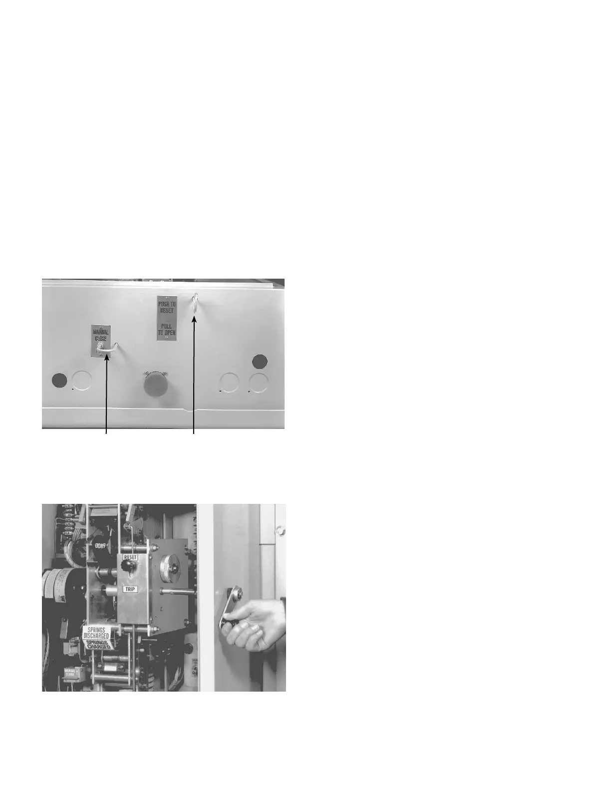
2. When closing spring status indicator reads SPRINGS
CHARGED, lift up the MANUAL CLOSE lever on the
operating mechanism, or pull the external MANUAL
CLOSE pullring to release the charged springs an close
the recloser.
ote:N Immediately upon closing, the motor will operate to
again charge the closing springs.
If motor operating power is not available the closing
springs may be charged by manually cranking the
mechanism until the closing springs status indicator reads
SPRINGSCHARGED:
1. Remove bolt and seal assembly from hole in right side
of cabinet.
2. Insert manual crank shaft through the cabinet wall
and onto the shaft protruding from the mechanism
(Figure6).
Manual close Manual trip
Figure 5. Manual operation pullrings
3. Crank the motor in a COUNTERCLOCKWISE direction
until the spring status indicator reads SPRINGS
CHARGED. Approximately 150 revolutions are required.
Figure 6. Manually charging closing springs
To open recloser
To release the opening spring either pull down the TRlP
RESET knob on the front of the operator mechanism or the
PULL TO OPEN pullring under the cabinet. Return knob or
pullring to the RESET position after the unit has tripped, to
enable the electronic closing circuit.
Insulation level withstand tests
High potential withstand tests provide information on the
dielectric condition of the recloser and the vacuum integrity
of the interrupters. Testing is performed at 37.5 kV rms
(75% of the rated low frequency withstand voltage of the
VSArecloser).
Test 1: Proceed as follows:
1. Manually close main contacts of recloser.
2. Ground recloser housing.
3. Connect all three bushings on one side of the recloser
together.
4. Apply proper test voltage to the connected bushings.
5. The recloser should withstand the test voltage for 60
seconds.
Test 2: Proceed as follows:
1. Manually close main contacts of the recloser.
2. Ground housing.
3. Ground outer two phase bushings (1-2 and 5-6).
4. Apply proper test voltage to center phase bushings (3-4).
5. The recloser should withstand the test voltage for 60
seconds.
Test 3: Proceed as follows:
1. Open main contacts of recloser.
2. Ground recloser housing.
3. Connect and ground all three bushings on one side of
the recloser.
4. Connect the other three bushings together.
5. Apply proper test voltage to the ungrounded bushings.
6. The recloser should withstand the test voltage for
60seconds.
7. Reverse the ground and test connections and apply test
voltage to the ungrounded bushings for 60 seconds.
8. The recloser should withstand the test voltage for
60seconds.
Test results:
These high potential withstand tests provide information
on the dielectric condition of the recloser and the vacuum
integrity of the interrupters.
 Loading...


