26
SPEAR™ Single-Phase Recloser System
INSTALLATION AND OPERATION INSTRUCTIONS MN280048EN June 2016
Customer connections for contact I/O module option
CAUTION
Equipment damage. Do not drill connection holes into
the top of the cabinet. Connection holes in the top
of the cabinet will allow moisture to seep into the
control and damage the components or cause control
misoperation. Failure to comply will void the control’s
factory warranty.
T249.0
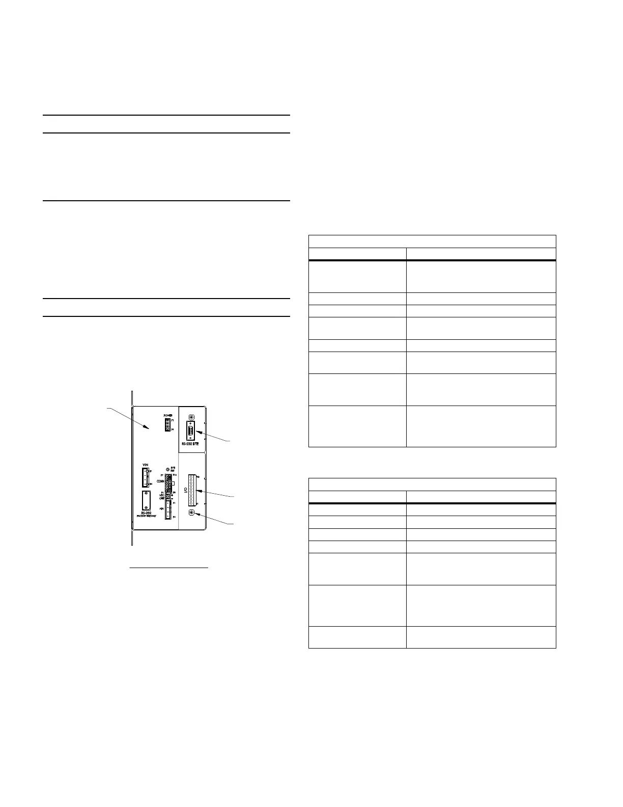
The Contact I/O module (Figure 23) permits connection of
contact-type input devices (switches, relays) and indicating
devices (relays, LEDs, lamps) to the SPEAR single-phase
recloser control to affect local Contact input/output (I/O). The
Contact I/O module accessory is used for supplementing
normal local controls and status indicators for Contact I/O
functions.
IMPORTANT
The control gives priority to TCC timing and issuing a trip
signal rather than changing the status of a Contact I/O
module output or responding to a Contact I/O module input.
Refer to Table 9 for I/O response times.
Figure 23.
FRONT VIEW
(DOOR REMOVED)
BOTTOM VIEW
FRONT VIEW
(WITH CONTROL AND DOOR
REMOVED FOR CLARITY)
RIGHT SIDE VIEW
BACK VIEW
MODULE SIDE VIEW
FEMALE
RECEPTACLE
FOR RECLOSER
CONTROL CABLE
INPUT RECEPTACLE
FOR RADIO
ANTENNA
RECEPTACLES
LATCHES WITH
PADLOCK
PROVISIONS
1.13
LIFTING LUG
10.63
MOUNTING
CHANNELS
1.12
9.84
PROVISIONS FOR
UP TO 5/8" MOUNTING
HARDWARE
GROUND LUG FOR
#4 TO #14 SOLID OR
STRANDED WIRE
12.01
VENT OPENINGS
6.00
22.60
1.69
20.87
17.72
1.46
.87
POWER SUPPLY
BATTERY
OPTIONAL RS-232
COMMUNICATION
PORT
CONTACT I/O
MODULE
CONTROL MODULE
SHIELD WIRE
CONNECTION
Contact I/O module
The Contact I/O module comes standard with each SPEAR
single-phase recloser control. This contains two factory set
inputs and two outputs for Contact I/O functionality. These
inputs and output contacts are not user programmable.
The SPEAR control does not support additional Contact I/O
modules.
Whetting voltage is supplied from VTC OUT (side of SPEAR
single-phase recloser control module) for the Contact I/O
inputs terminal block on the back panel as shown in Figure
24.
The two Contact I/O outputs are Form C relay contacts,and
are of non-latching type. Refer to Table 10 for output fusing
recommendations.
ote:N Latching is defined as an output that retains its
status when control power is removed.
Non-latching is defined as an output that returns to a
default status when control power is removed.
ote:N Following a firmware upgrade the Contact I/O
module output relays will revert to the de-energized
state.
Table 9. Contact I/O option module input ratings
Specification Value
Minimum detection level
10 V (AC rms or DC) (50 or 60 Hz)
Using control-supplied whetting voltage is
recommended.
Maximum applied voltage 250 VAC, rms, or 125 VDC
Nominal input loading 2 mA per input (internally current limited)
Typical control response time
50 msec (Note: Protection tasks take priority
over input activity.)
Minimum input pulse time 250 msec
Minimum transition time
between pulse inputs
250 msec
Input protection
Shunting type using MOVs and capacitors.
Optical isolation from input to system.
(1500 VAC, rms)
Hi-pot capability
3.150 kV DC for 1 second, from one input set
to the next or from one pin to chassis, but
not across the two terminals of a single input
(due to internal MOVs).
Table 10. Output ratings
Specification Value
Maximum switching voltage 250 VAC, rms or 125 VDC
Maximum switching loading Refer to Figure 25.
Maximum pickup time 8 msec (not including control response time)
Maximum release time 15 msec (not including control response time)
Output protection
Shunting type using MOVs and capacitors.
1500 VAC, rms isolation between coil and
contacts
Hi-pot capability
3.150 kV DC for 1 second, from one output to
the next or from one pin to chassis, but not
across the two terminals of a single output
(due to output protection).
Fusing
Outputs are not internally fuse-protected.
Customer-supplied fusing is recommended.
 Loading...


