Catalog data MN650002EN
Effective February 2019
Deadbreak apparatus connectors
Compression connector procedures
Equipment provided
•
BOL-T Connector Assembly Kit includes:
• T-body
• Cable adapter
• Insulating plug with cap
• Compression connector
• Silicone lubricant
• Threaded stud
• Instruction sheet
Tools required
•
Torque wrench
•
5/16" Hex wrench for splice application
•
Cable stripping tools
Prepare the cable
Step 1.
Train cable
•
Position cable vertically so that it is centered between
apparatus bushing and parking pocket, parallel to, and 7"
(178 mm) from apparatus frontplate.
•
Provide adequate cable slack for cable movement
between standoff bushing and apparatus bushing.
•
Support cable as needed to maintain position.
•
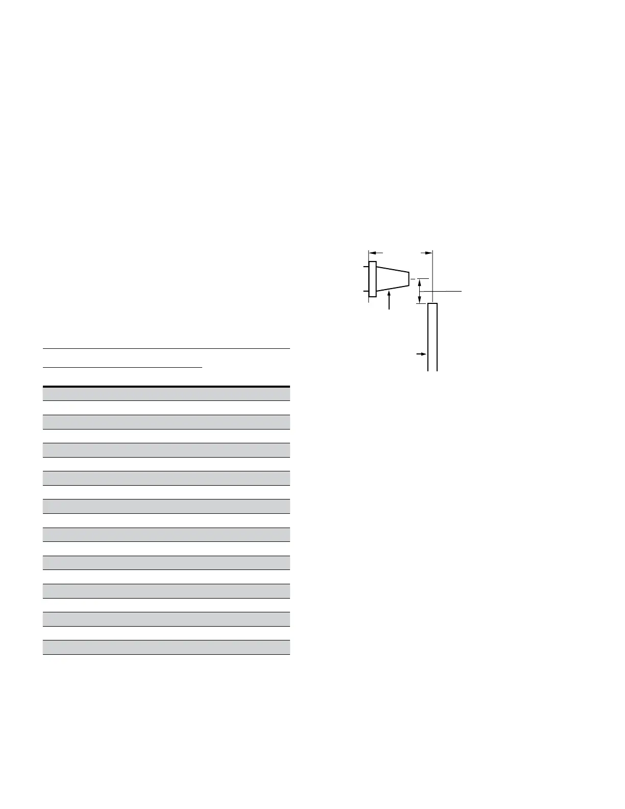
Cut cable 1 3/4" (44 mm) from centerline of bushing.
Refer to Figure 14.
Figure 14. Line illustration for cable training.
Bushing
Cable
1 3/4" ± 1/4"
(44 mm ± 6 mm)
7"
(178 mm)
Table 3. Conductor size and type
Compression connector
Concentric or
Compressed Compact or Solid
Compression
conductor code
AWG or
kcmil mm
2
AWG or
kcmil mm
2
No Connector 00
#2 35 1 - 11
#1 - 1/0 50 12
1/0 50 2/0 70 13
2/0 70 3/0 - 14
3/0 - 4/0 95 15
4/0 95 250 120 16
250 120 300 - 17
300 - 350 - 18
350 - 400 185 19
400 185 450 - 20
450 - 500 240 21
500 240 600 300 22
600 300 700 - 23
650 - 750 - 24
750 - 900 - 25
900 - 1000 500 26
1000 500 - - 27
1250 630 - - 28
8
600 A 35 kV class BOL-T connector assembly installation instructions for MN650002EN February 2019
 Loading...


