3
ELSG Full-Range Current-Limiting Fuse
RE-FUSING INSTRUCTIONS MN132017EN November 2016
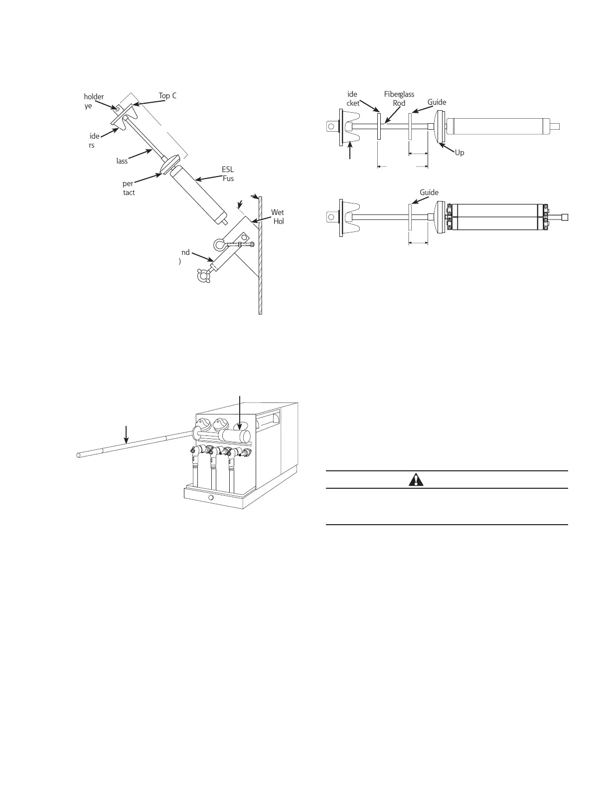
Figure 6.
Bail Assembly
(Loosened and
Lowered)
Top Cover of Handle
Assembly
Handle Assembly
Wetwell
Holder
ESLG
Fuse
Upper
Contact
Fiberglass
Rod
Fuseholder
Eye
Cap Guide
Fingers
45°
Removal of handle assembly with fuse from
wetwell.
Replace ELSG fuse on handle assembly
Figure 7.
ELSG
Fuse
Shotgun
Stick
Place fuse assembly in clean drip pan.
The ELSG fuse is mounted to the handle assembly as
shown in Figure 6. Remove the ELSG fuse from the
operating handle assembly.
Attach a new ELSG fuse to the operating handle. Tighten
to 15 foot-pounds torque using 5/8”wrench flats on the
side of holder eye on handle assembly.
ote:N For 2-inch diameter triple barrel ELSG fuse as shown
in Figure 1, observe top adapter plate decal with
insertion instructions.
In addition, 15.5 kV and 23 kV rated fuses with 2-inch
diameter single-barrel or double barrel use guide brackets
(supplied with fuse) on the handle assembly. (See
following steps for proper installation of handle assembly
guide brackets.)
3.5 in.
(89mm)
3.5 in.
(89mm)
7.5 in.
(191mm)
Bracket
Rod
Guide Bracket
Guide Bracket
Single
Barrel Use
Double
Barrel Use
Upper Contact
Cap Guide
Fingers
Figure 8. Fuse assembly consists of handle assembly
plus ELSG fuse. (Plus guides, where applicable.)
* 15.5 kV and 23 kV rated fuses use guide bracket (catalog no.
3439216B02).
ote:N Wetwell holder of fuse being replaced is
deenergized. Other holders and, thus leads within
the switchgear, may be energized.
The guide(s) is to be installed on the fiberglass rod of the
handle assembly as shown in Figure 8 to guide the fuse
straight into the wetwell holder.
One guide is included for the 15.5 kV and 23 kV
2-inch
diameter double barrel fuse.
Two guides are included for the 15.5 kV and 23 kV
2-inch diameter single barrel fuse.
The spacing of the guides as shown in Figure 8 are critical
to within ± 1/2 inch.
CAUTION
Failure to use the guide(s) on the handle assembly as
shown may allow the fuse to contact an energized lead
and operate during installation or removal.
Position and securely tighten the guide(s) to the
fiberglass rod of the handle assembly, as illustrated for
the appropriately rated fuse. When two guides are used
for the single barrel fuse, rotate the upper guide 60°
out from the position of the lower guide as shown in
Figure 9.
 Loading...


