7
Replacement of Cover Gasket for Padmount Switchgear Side-Hinge-2 Models
FIELD SERVICE INSTRUCTIONS MN285009EN April 2019
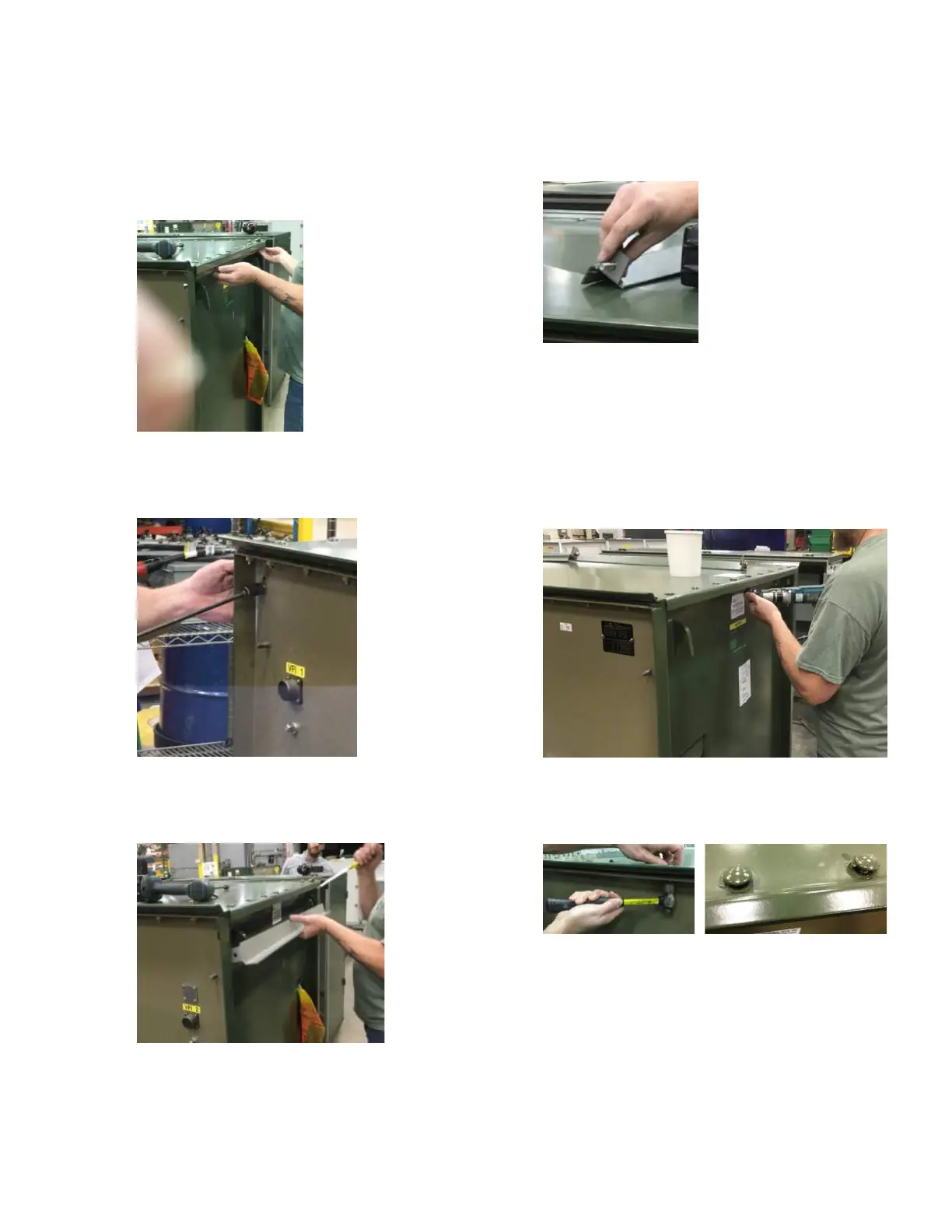
4. Remove the side cover Nut-Guards
4.1 Remove the side cover Nut-Guard fasteners on both
sides of the main unit (Figure 31).
Figure 31.
4.2 Remove the cover Nut-Guard fastener on both Face
Plate upper corners (Figure 32).
Figure 32.
4.3 Remove the side cover Nut-Guards on both sides of
the main unit (Figure 33).
Figure 33.
4.4 Return the fastener hardware to the Nut-Guard
(Figure 34) for replacement later.
Figure 34.
5. Remove the cover fasteners
5.1 Using a 9/16-inch socket on a right-angle electric driver
tool, remove the silicon-bronze nuts and Belleville
washers from all cover bolts (Figure 35).
Save all hardware in containers/buckets for reuse.
Figure 35.
5.2 Remove all stainless steel cover bolts. Tap on the bolt
to break the paint bond at the bolt-head (Figure 36).
Figure 36.
5.3 Remove all bolt gaskets that are stuck on the cover:
5.3.1 Use a putty-knife scraper and wire-brush to
remove the loose paint peeled in these areas
to provide a smooth transition between the
painted and unpainted surface areas.
5.3.2 Clean all bolt hole areas on the cover surface
with isopropyl alcohol.
 Loading...


