8
Replacement of Cover Gasket for Padmount Switchgear Side-Hinge-2 Models
FIELD SERVICE INSTRUCTIONS MN285009EN April 2019
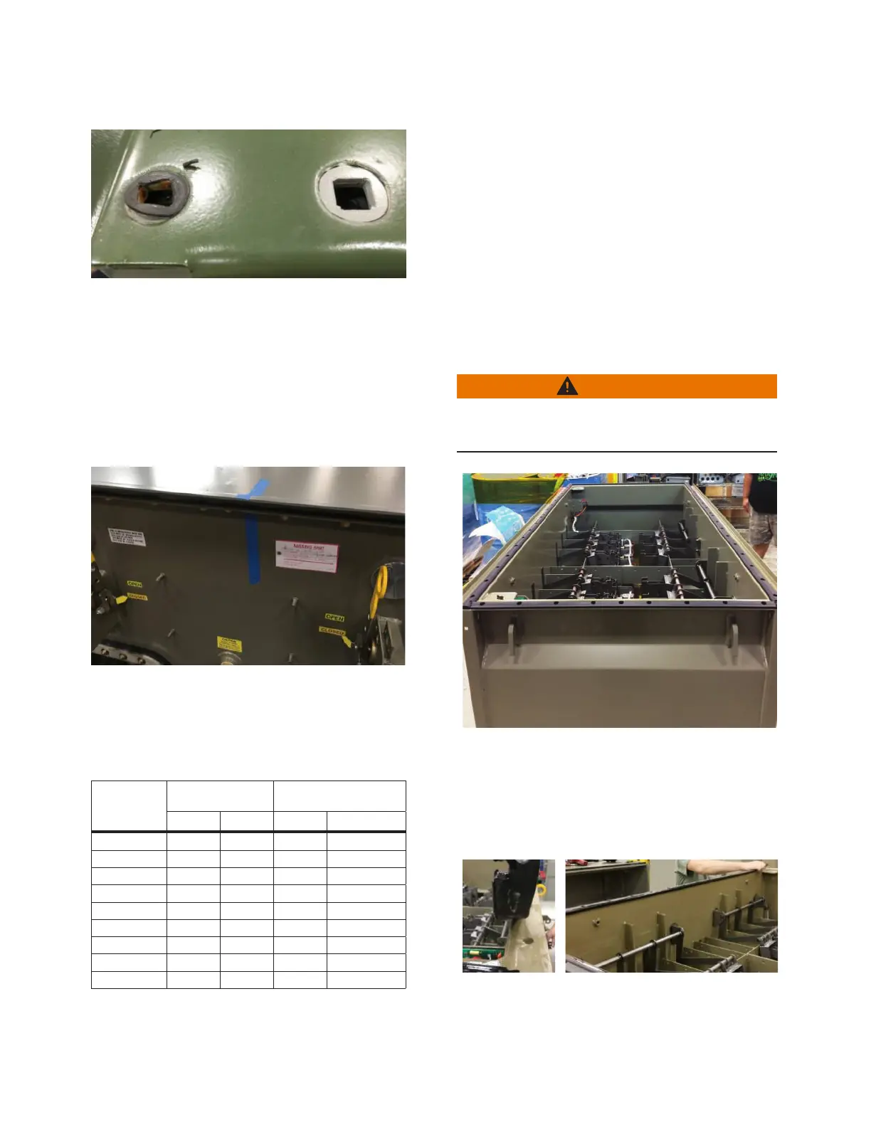
Figure 37. Typical condition of bolt hole area before
cleaning. On the left, the bolt hole shows
the bolt gasket adhered to the cover; on
the right, the bolt gasket lifted off with the
bolt when the bolt was removed.
6. Remove the cover
6.1 Place removable blue masking tape on one side of the
cover and the tank (Figure 38) so you can identify the
original orientation later, during re-installation of cover.
Figure 38.
6.2 Measure the tank cover’s front face width and depth;
then refer to Table 4 on page 8 to determine the
cover’s weight.
Table 4. Reference: Cover Weight (lbs)
Face width
(inches)
Depth (inches)
Mild or Stainless Steel
Weight (lbs)
Min Max Min Max
32 18 32 35 57
40 24 43 54 89
47 18 39 49 94
62 18 58 63 171
70 24 58 89 274
74 24 46 126 233
84 24 53 142 297
94 28 46 179 289
104 24 46 173 317
6.3 Prepare to remove the cover:
6.3.1 Make the necessary arrangements to handle
the cover’s weight (for example, enlist the help
of another person).
6.3.2 Decide where to place the cover after it is
removed and set up that area appropriately.
For example, set up workstands to hold the
cover, or identify a clean surface of adequate
size.
6.3.3 Ensure that you have a clear path to carry the
cover from the unit to the identified location.
6.4 Lift the cover off of the tank (Figure 39) and place it off
to the side on workstands or upside-down on a clean
surface.
WARNING
Heavy object. To avoid muscle strain or back injury,
use lifting aids and proper lifting technique when
lifting tank cover.
Figure 39.
7. Remove the cover gaskets
7.1 Starting at the corner of a tank flange, grasp the end
of one gasket and lift it up (Figure 40).
Figure 40.
 Loading...


