Page 35
614-20306-00 - 9SX 0-6 KVA EMEA_EN
4. Interfaces and Communication
4.5 Communication ports
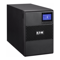
Connection of RS232 or USB communication port
Independent Multiplexed
Communication Bay USB RS-232
Any connectivity card Available Not in use
Any connectivity card Not in use Available
1. Connect the RS232
17
or USB
18
communication cable to the serial or USB port on the computer
equipment.
2. Connect the other end of the communication cable
17
or
18
to the USB
10
or RS232
9
communication
port on the UPS.
The UPS can now communicate with EATON power management software.
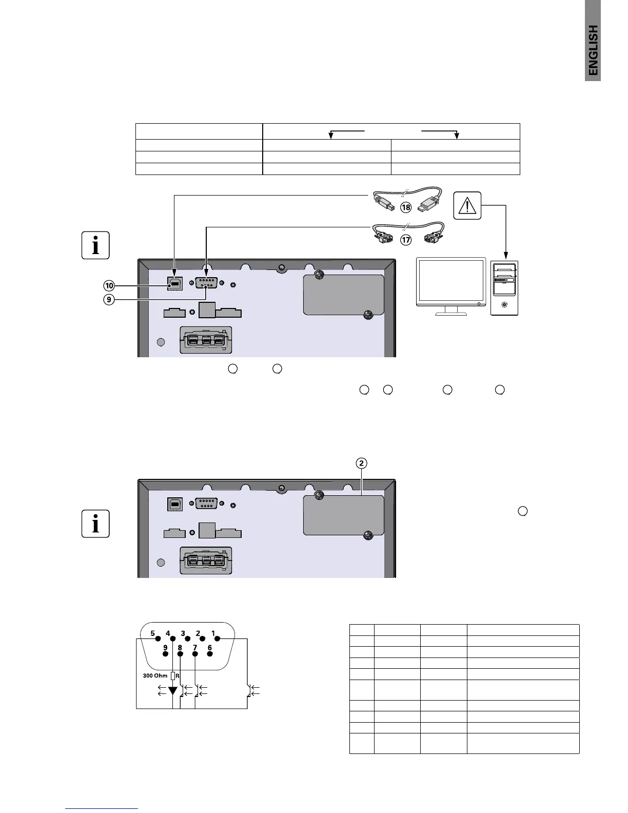
Installation of the communication cards (optional)
It is not necessary to shutdown the UPS
before installing a communication card.
1. Remove the slot cover
2
secured by
screws.
2. Insert the communication card in the
slot.
3. Secure the card cover with the 2 screws.
Characteristics of the contact RS232 communication port
Contact characteristics (optocoupler)
• Voltage: 48 V DC max
• Current: 25 mA max
Pin Signal Direction Function
1 Bat Low Output Low Battery Output
2 TxD Output Transmit to external device
3 RxD Input Receive from external device
4 I/P SIG Input -
5GNDS - Signal Common tied to
chassis
6 PNP Input Plug and Play
7
8BAT ModeOutput -
9 +5V Output Power supply for external
signal or options
 Loading...