7
5 Installation
Installation and Operating Instructions CGLine+ Web-Controller 40071860236 (E) February 2019 www.eaton.com
System button
3
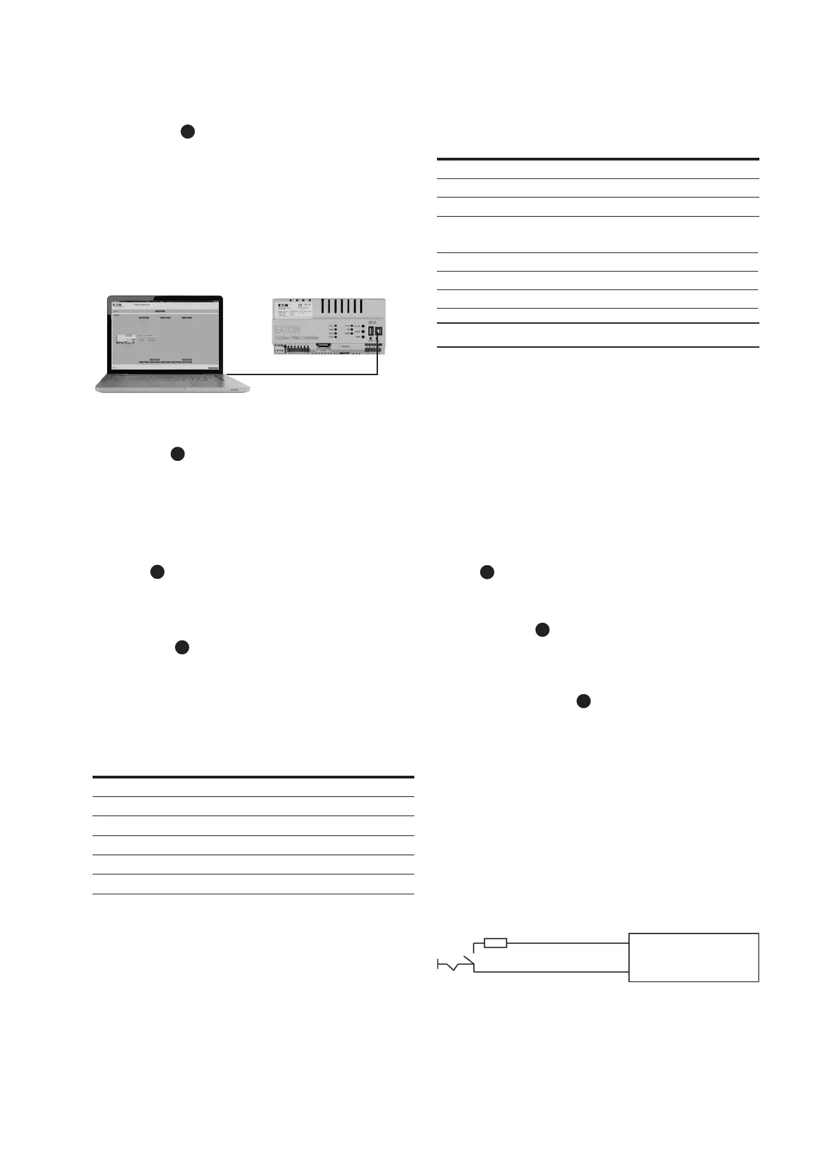
The system button enables the CGLine+ Web-Controller to be
connected to a PC. If pressed for ~ 3 seconds, the green USB2
LED turns on and an external storage from Windows will be
detected. An access via PC software will be possible now. To
remove the controller the following steps are required:
1. Remove external hard drive via windows
2. Press system button for 3 seconds, green USB2 LED will
turn off
Fig. 3. Connecting the controller to a laptop with CGLine+
PC-Software via USB A-B
Reset button
3
The reset button resets the CGLine+ Web-Controller (not fac-
tory default). For this purpose, the button must be pressed
and held for >1 second.
5.2.3 Connections
230 V/AC
6
Connection terminals for power supply 230 V/ AC with 50/60
Hz.
CGLine+ Bus:
7
The Web-Controller is compatible to the old CGLine technlogy.
If one or more CGLine luminaires are connected, the CGLine
compatible mode is active. Following luminaires can be con-
nected:
Table 2. Max. number of luminaires to be connected
Line No. CGLine CGLine+
4 lines 2 lines
1 100 200 400
2 100 200 400
3 100 200 -
4 100 200 -
Total 400 800 800
Polarity D1/D2 to the luminaires must not be observed. Cable
routing for CGLine bus: 2-core bus line, unshielded, free bus
topology possible.
Table 3. Cable length/line
Cross-section Length Total lines
0.5 qmm 260 m 660 m
1.0 qmm 520 m 1320 m
1.5 qmm 800 m 2000 m
Table 4. Electrical data/line
Power supply bus 25 V
Max. permissible voltage drop 6 V
Bus current 300 mA
NOTE
In case of a communication failure with a luminaire please
check the following:
1. Check the proper connection of the bus line at the lumi-
naire’s connector
2. Check the correct bus voltage at the luminaire (see table 4.)
3. In case the voltage is correct and the communication failure
still exists: Check the bus line resistance which shouldn’t
exceed 32 Ohm. For that please disconnect the relevant line
from the web-controller, apply a short cut between the bus
contacts at the affected luminaire and measure the resis-
tance at the other end of the line.
RS485
8
No function. Only for french market.
LAN connection
9
Ethernet connection via RJ45 socket. A LAN patch cable must
be used for direct connection of a PC/notebook.
Blocking input (S1/S2):
All connected luminaires can be blocked via the blocking
input, meaning the luminaires are switched off and the emer-
gency light function deactivated, for example for idle operat-
ing times.
Connection is via a key switch or relay (e.g. alarm system). To
guarantee reliable operation from short-circuit or interruption
of the blocking line, this input is equipped with differential
loop monitoring (static current), meaning a 1kOhm resistance
must be integrated for blocking that defines the static current.
Connection example:
With closer contact
S1 CGLine
S2 Interface
With opener contact

 Loading...