Instruction Bulletin IB00414001Y
Effective January 2015
Complete Home Surge Protection
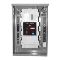
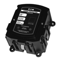
Figure 1. Panel Mount Installation (1)/Installation au panneau (1)
(1)/Instalación en el centro de cargo
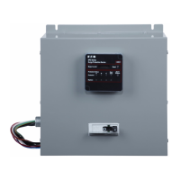
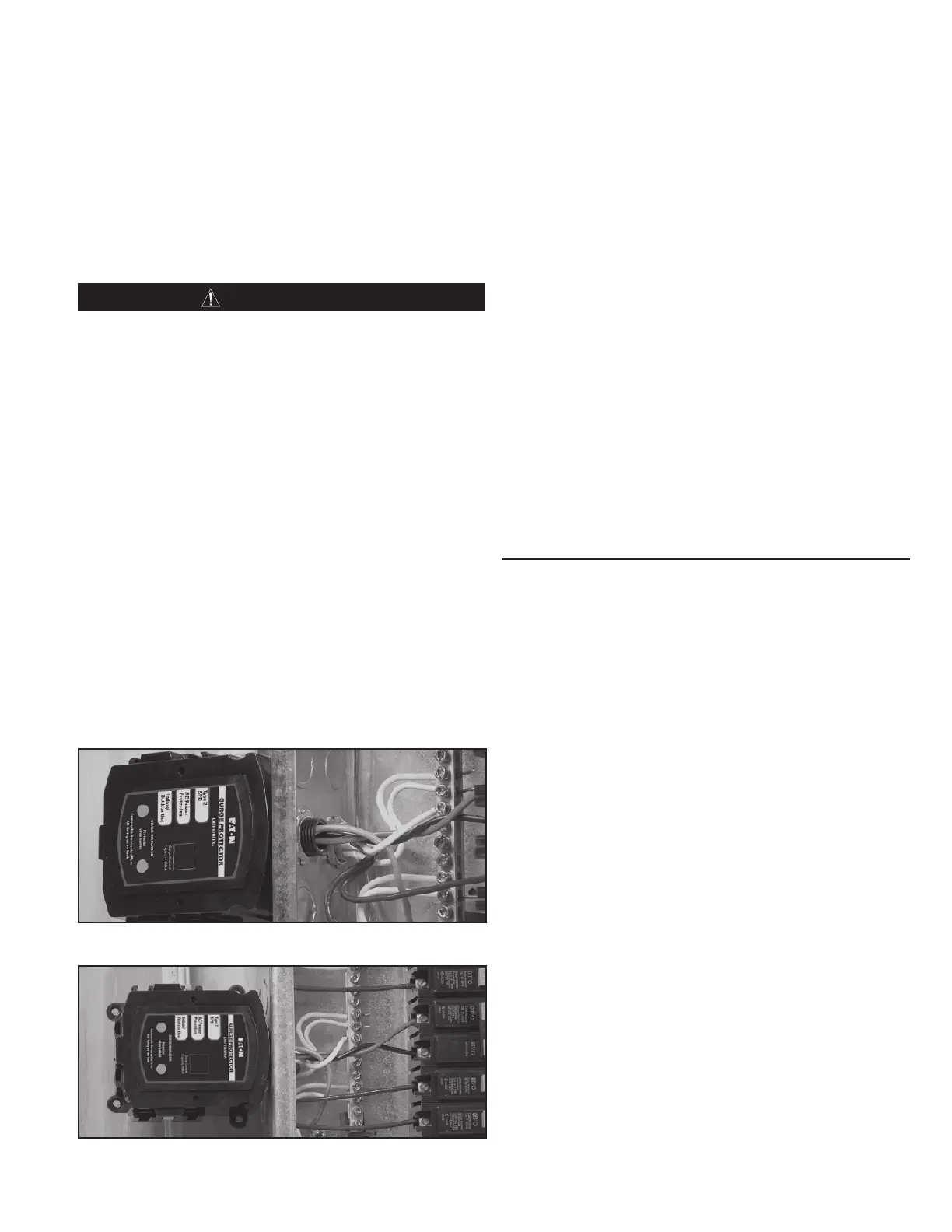
Figure 2. Panel Mount Installation (2)/Installation au panneau (2)
(2)/Instalación en el centro de carga
Finished Wall (Flush Mount) (Figure 3)
9. Attach the CHSP either by Panel Mount or Surface Mount, and
attach the optional Flush Mount lid on the surface of the CHSP.
10. Install the supplied two 4-40 mounting screws to firmly secure
the Flush Mount lid. Continue with final installation Step 11.
Outdoor Installation (Figures 4 and 5)
11. Use only a raintight rated coupling and conduit, made from
corrosion resistant material, to connect the CHSP to the
outdoor loadcenter.
IMPORTANT
•
Be sure to follow all U.S. National Electrical Code, state, and local
codes, or other applicable country codes.
•
To avoid fire, shock, or death, turn OFF power at circuit breaker
or fuse and test that power is OFF before wiring.
•
When connecting the wires from the CHSP to the electrical
system, cut the wires as necessary to keep them as short as
possible - 12 inches (30 cm) or less is recommended.
•
To maximize the CHSP’s performance, twist and bind the wires
together to reduce the impedance of the wire (one twist / inch).
Wiring the CHSPT2SURGE/CHSPT2ULTRA
(Figures 1 and 6)
12. Use care in stripping insulation from the conductors. Cut off any
excess wire and strip approximately 1/2-inch (1.25 cm) from all
four wires.
13. Connect the White wire to the neutral bus bar.
14. Connect the Green wire to the ground bus bar.
15. Connect the Black and Red wire to the 2-pole circuit breaker
installed in Step 4. Connect the Black wire to one terminal and
the Red wire to the other terminal. Do not install both wires
on the same terminal.
16. Check that all connections are correct (refer to wiring diagram
Figure 6).
17. Replace loadcenter cover.
18. Restore electrical power. Switch main breaker to ON position.
19. Reset the 2-pole circuit breaker supplying power to the CHSP
to the ON position. The LED indicator lights should illuminate.
Note: If the 2-pole circuit breaker supplying power to the CHSP
trips, replace the unit.
Operations / Troubleshooting
Power Up and System Checkout
Apply system power. The LED should light.
If the connected LED does not light, remove power, check connec-
tions, and test again. If the LED still does not light, contact Eaton’s
Technical Resource Center at 1-877-ETN-CARE, option 2, then
option 1.
Routine Operation
After system power has been applied, the CHSP automatically
begins to protect downstream electrical devices from damaging
voltage transients.
With all phase voltages present, the LED indicator reports the status
of the protection elements and is active when all of them are intact
and providing protection. Any loss of protection is signaled when the
LED extinguishes.
The device is not repairable and contains no user serviceable parts.
If the unit fails, as evidenced by the LED turning OFF, the unit must
be replaced.
Instructions d’installation et d’emploi
Merci de votre achat d’un parasurtenseur complet résidentiel CHSP
Eaton
®
. Ce produit fait partie du système parasurtenseur modulaire
CHSP comprenant les éléments suivants:
•
Le module CA CHSPT2SURGE ou CHSPT2ULTRA, conçu pour
protéger les charges électroniques et électriques résidentielles
des courants transitoires et des surtensions sur la ligne de
courant alternatif. Ce module est destiné à un usage à
la fois intérieur et extérieur.
•
Le module CHSPCABLE de protection des câbles coaxiaux de
télévision, de télévision par satellite et autres appareils à câbles
coaxiaux contre les courants transitoires et les surtensions. Ce
module est à usage intérieur seulement. Les installations en
extérieur nécessitent un boîtier extérieur à acheter séparément
(accessoire CHSP3RTELCABLE).
Le système Eaton est conçu pour être facilement installé dans les
maisons nouvellement construites comme plus anciennes. Par
exemple, dans la construction neuve, lorsque les câbles coaxiaux
sont acheminés à proximité du tableau électrique, les modules
CHSP peuvent être assemblés en utilisant la caractéristique unique
de connexion rapide trouvé sur chaque module de protection, pour
un système de protection contre les surtensions parfaitement con-
figuré (voir les figures 8, 9, et 10).
Ces instructions ne recouvrent pas tous les détails sur le parasur-
tenseur concernant les variations et combinaisons, l’entreposage,
l’intensité de courant, l’installation, la vérification, l’entretien ou
l’utilisation sécuritaire. Si vous avez besoin d’un complément
d’information au sujet d’une application ou d’une installation particu-
lière qui n’est pas expliquée dans cette notice d’emploi, veuillez com-
muniquer avec le Technical Resource Center (Centre des ressources
techniques) d’Eaton en composant le 1-877-ETN-CARE, option 2, puis
option 1.
3
EATON CORPORATION www.eaton.com
 Loading...