IF 1767 • 09/15 Copyright
©
2015, Eaton’s Crouse-Hinds Division Page 3
2. MECHANICAL INSTALLATION
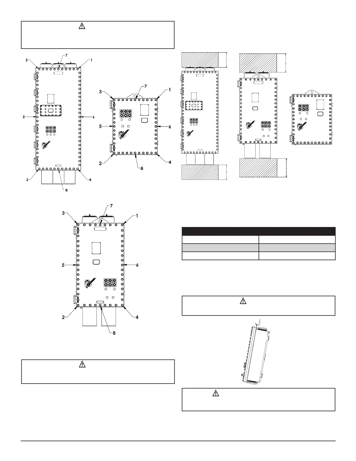
2.1 AIRFLOW PROVISIONS - INSTALLATION
DRAWING
It is imperative that the enclosure be well ventilated to ensure reliable
performance. Adequate space around the intake and exhaust of the
enclosure MUST be accommodated. Eaton’s Crouse-Hinds Division
recommends ‘x’ be a minimum of 12 inches (0.3 meters).
2.2 WEIGHTS
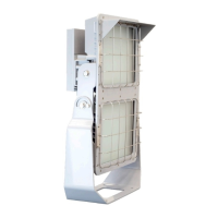
2.3 LIFTING
1. Remove top and sides from shipping crate.
2. Remove lag bolts from enclosure mounting feet
3. Use the dedicated lifting eye to mount enclosure on suitable
mounting surface. Select a mounting location that will provide
suitable strength and rigidity for supporting the enclosure and all
components.
Figure 1
Enclosure Weight (Approx.)
Size 1 (1-5 HP) 350
Size 2 (7-30 HP) 550
Size 3 (40-100 HP) 1200
CAUTION: UNBALANCED LOAD
To avoid personnel injury, utilize the dedicated lifting eye and handle
appropriately to ensure safe installation.
WARNING
To avoid cooling system malfunction and personnel injury, be sure
to torque the first eight (8) cover screws sequentially per Figure 1
before torquing the remaining screws.
WARNING
To avoid personnel injury and property damage, DO NOT remove or
modify the control pad viewing window.
CAUTION
Do not attach shrouds or pre-filters until after enclosure is mounted.

 Loading...