IF 1767 • 09/15 Copyright
©
2015, Eaton’s Crouse-Hinds Division Page 8
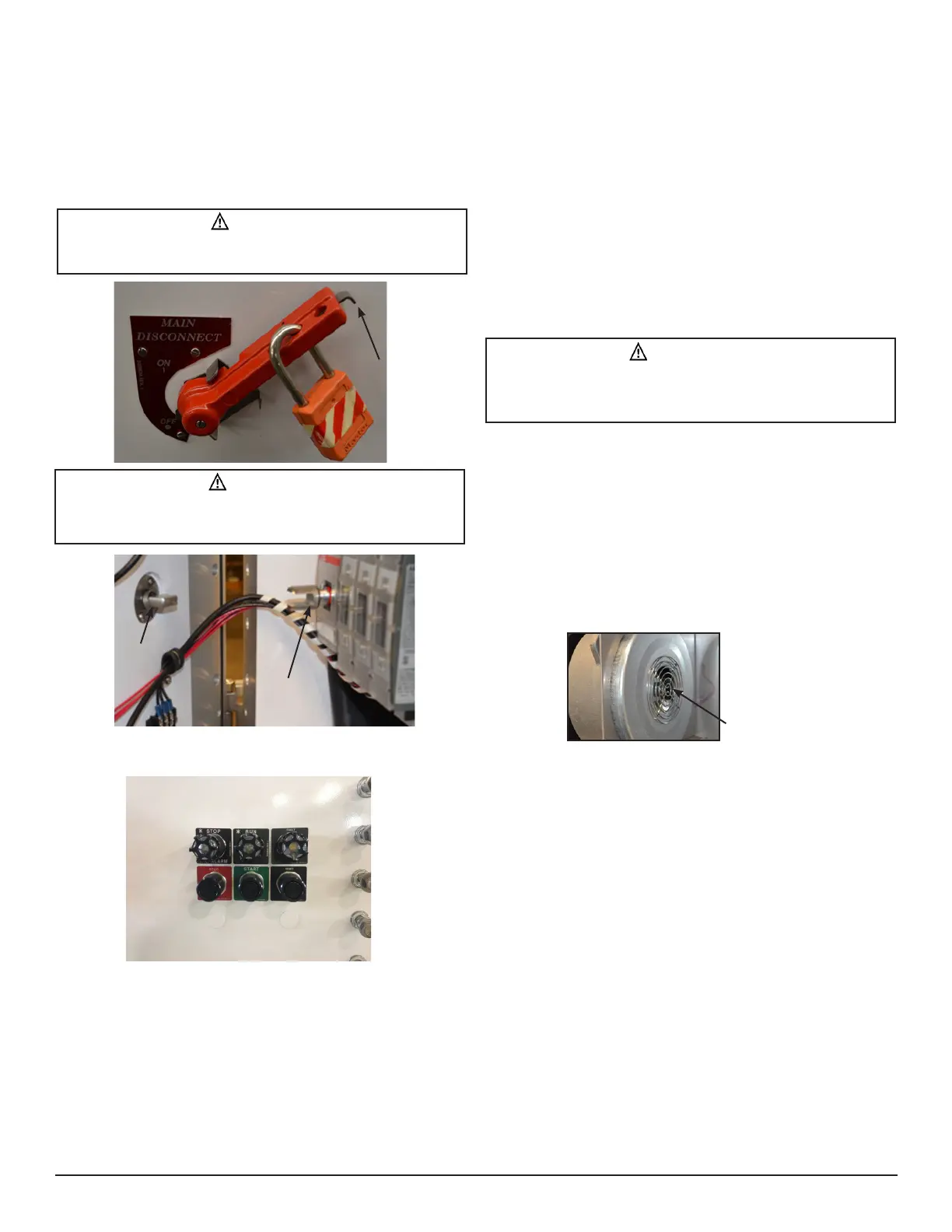
4.2 DISCONNECT AND LOCKOUT/TAGOUT
The disconnect handle is furnished with three (3) holes for lockout/tagout
purposes.
1. Turn handle to the ‘off’ position.
2. Depress lockout tab at the end of the handle.
3. Install OSHA approved lock or tag.
4. Release lockout tab.
4.3 DRIVE CONTROLS AND STATUS INDICATION
Three (3) momentary pushbutton operators control the START, STOP and
[fault] RESET of the drive. They are wired to the drives digital inputs and
are configured to be the “local control place.”
Three (3) LED pilot lights indicate the drives status – Red = Stopped,
Green = Running, Amber = Drive Fault. These are wired to the drive’s
relay outputs.
Note: As standard, speed control must either be programmed from the
drive’s keypad, by remote analog signal (customer supplied) or by using
the on board or option card communications capabilities.
4.4 PT (POTENTIOMETER) AND LR (LOCAL/
REMOTE)
• Suffix options PT and/or LR, when ordered, are wired to the drives
I/O for additional user control.
• For suffix PT, a 10K-ohm potentiometer is connected to AI1, and is
configured to be the local (primary) speed reference source.
• For suffix LR, a 2-position selector switch is connected to DI7 & 8,
and is configured to switch between local and remote operation.
• Parameters for these options, shown in section 7.1, are set up
at the factory. Refer to drive manufacturers manual for further
information.
5. MAINTENANCE
5.1 DRIVE MAINTENANCE
Periodic cleaning of the drive fan and heat sink is recommended.
Removal of the drive from the enclosure is recommended to ensure
debris does not obstruct the cooling system. Refer to the drive
manufacturer’s manual for additional maintenance recommendations and
specific instructions.
5.2 COOLING SYSTEM MAINTENANCE
1. Clean pre-filter periodically. Remove pre-filter and rinse with water
as needed.
2. Clean sintered filter as needed. Use of abrasives on the
explosionproof filters may compromise the integrity of the cooling
system.
3. Clean/inspect blower intake.
4. Perform visual, electrical and mechanical checks on all components
on a regular maintenance schedule. NFPA 70B recommends
maintenance intervals not exceeding 2 months.
5. Visually check for any damage to the filter assemblies, flat joints,
threaded joints, journal joints and window.
6. Visually check for evidence of excessive heating within the
enclosure.
7. Mechanically check that all parts are properly assembled and
operating mechanisms are in proper working condition.
8. Verify airflow provisions are maintained per Section 2.1.
WARNING
To avoid ignition of explosive atmospheres, all circuits must be
de-energized before opening cover.
CAUTION
To avoid damage to the integral disconnect operating mechanism,
be sure the disconnect coupling is in the off position before closing
cover.
CAUTION
To avoid cooling system malfunction and cooling system failure, be
sure to vacuum debris from the enclosure before energizing. NEVER
use forced air for the removal of debris from this enclosure.
Blower
Intake
Lockout Tab
Disconnect
Coupling
‘OFF’
Position
Disconnect
Shaft

 Loading...