9. Properly reseal the hand-hole cover, being careful not to
damage the cover or the gasket.
10. Connect the control cable to the connector at the
bottom of the junction box.
11. Pull a vacuum on the unit for at least one hour (2 mm
of vacuum or better) after the unit is completely refilled
with fluid.
ote:N If vacuum processing is not available, allow the
entire internal assembly to soak in fluid for at
least five days before energizing.
Spare parts
Ordering Information
When ordering replacement parts or field-installation
accessories for your Eaton voltage regulator, provide the
following information:
Regulator serial number (found on nameplate)
Regulator catalog number (found on nameplate)
Part number (not required)
Photo of part is helpful
Description of each part
Quantity of each part required
Refer to the following Service Information documents for
information on Eaton’s Cooper Power series tap-changer
maintenance and replacement parts:
MN225072EN, QD3 Quik-Drive Voltage Regulator
Tap-Changer Manual
MN225012EN, QD5 Quik-Drive Voltage Regulator
Tap-Changer Manual
MN225011EN, QD8 Quik-Drive Voltage Regulator
Tap-Changer Manual
Troubleshooting
For troubleshooting instructions, refer to Service Information
MN225003EN, CL-7 Voltage Regulator Control Installation,
Operation, and Maintenance Instructions. The procedures
in this section provide terminal markings for a single-phase
control. If troubleshooting is being performed on a regulator
with a multi-phase control, the terminals corresponding
to the phase in question should be used. See Table 7 for
assistance in identifying the correct terminals.
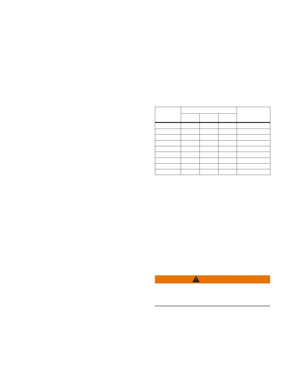
Table 7. Single-phase and multi-phase control back-
panel markings
Single-Phase
Control
Markings
Multi-Phase Control Markings
FunctionVR1 VR2 VR3
V1 V1A V1B V1C Load-Side PT
V6 V6A V6B V6C Differential PT
C CA CB CC CT Shorting Switch
C2 - - - CT +
C3 - - - CT +
R1 R3 R-B R-C Motor Raise
L1 L3 L-B L-C Motor Lower
G G G G Ground
HS HS HSB HSC Holding Switch
For additional assistance, call the Voltage Regulator Support
line at 866-975-7347 (calls from outside the U.S.:262-896-
2591) or e-mail questions to RES-VRSupport@Eaton.com.
Regulator control reverse power flow test
Purpose
The purpose of this procedure is to test the voltage
regulator and control to ensure correct operation in
response to reverse power flow.
Required equipment
Clamp-on ammeter
Appropriate cable leads
2 – 120 V variable power supplies
Procedure
WARNING
Hazardous Voltage. This procedure must only be
performed on a regulator that has been removed from
service. Failure to comply can cause serious injury or
death.
1. Remove the unit from service as described in
“Removal from service” on page 11.
29
VR-32 and EVER-Tap™ Voltage Regulator
InstallatIon, operatIon, and MaIntenance InstructIons MN225008EN June 2020

 Loading...