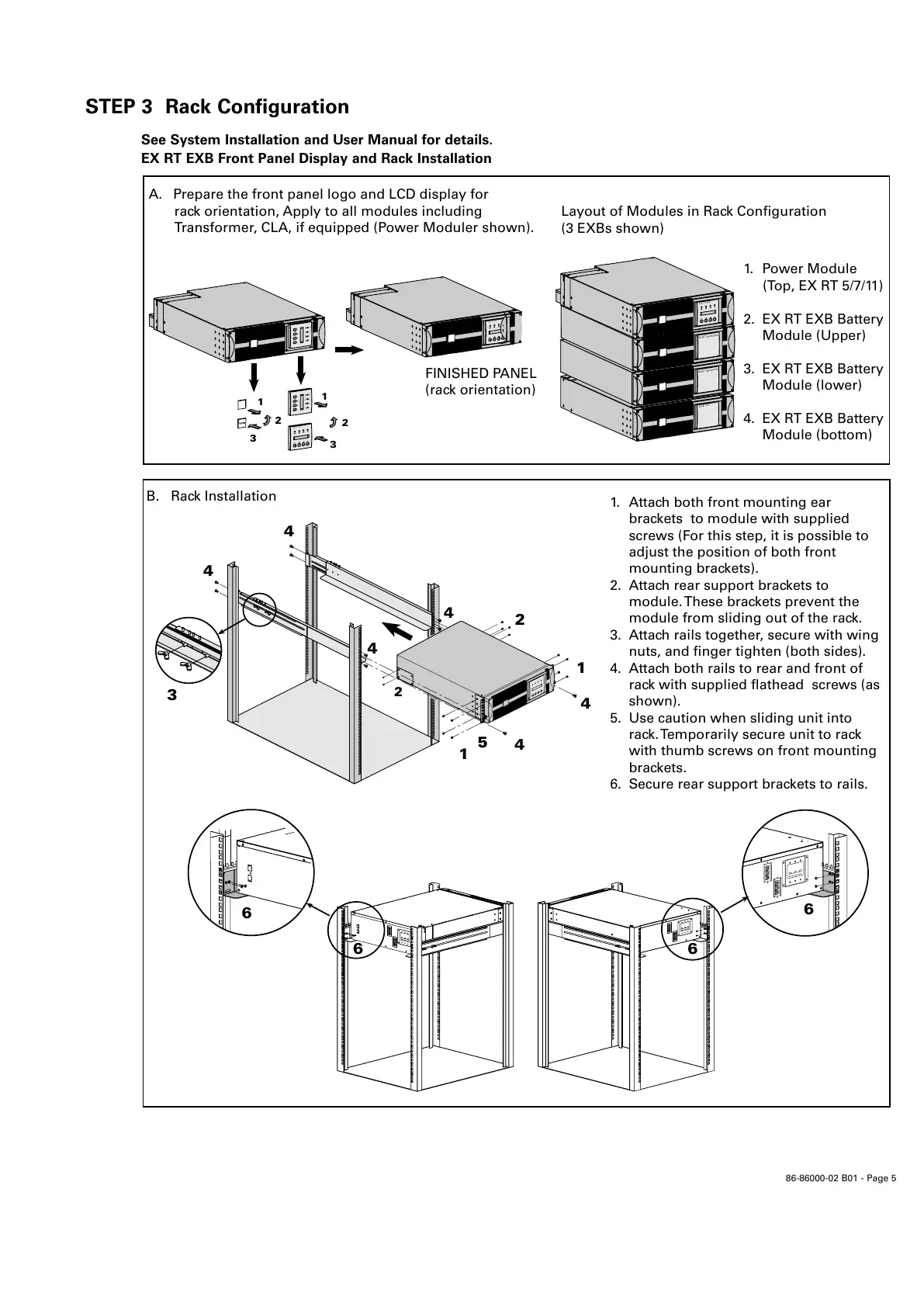
STEP 3 Rack Configuration
See System Installation and User Manual for details.
EX RT EXB Front Panel Display and Rack Installation
E
X 1
1
R T
O
F
F
O
N
E
X
1
1
R
T
O
F
F
O
N
E
X
1
1
R
T
O
F
F
O
N
E
X
1
1
R
T
O
FF
O
N
1
2
3
FINISHED PANEL
(rack orientation)
1
2
3
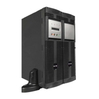
A. Prepare the front panel logo and LCD display for
rack orientation, Apply to all modules including
Transformer, CLA, if equipped (Power Moduler shown).
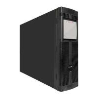
EXB
RT
Layout of Modules in Rack Configuration
(3 EXBs shown)
EX RT
Transform
er
EX
RT Transf
ormer
O
FF
ON
EX 1
1 RT
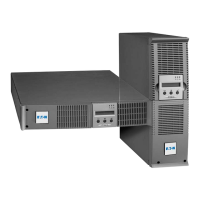
B. Rack Installation
3
4
4
4
4
2
2
1
4
4
5
1
6
6
6
1. Attach both front mounting ear
brackets to module with supplied
screws (For this step, it is possible to
adjust the position of both front
mounting brackets).
2. Attach rear support brackets to
module. These brackets prevent the
module from sliding out of the rack.
3. Attach rails together, secure with wing
nuts, and finger tighten (both sides).
4. Attach both rails to rear and front of
rack with supplied flathead screws (as
shown).
5. Use caution when sliding unit into
rack. Temporarily secure unit to rack
with thumb screws on front mounting
brackets.
6. Secure rear support brackets to rails.
6
1. Power Module
(Top, EX RT 5/7/11)
2. EX RT EXB Battery
Module (Upper)
3. EX RT EXB Battery
Module (lower)
4. EX RT EXB Battery
Module (bottom)
 Loading...