Customer connections for contact i/o
moduleoption
CAUTION
Equipment damage. Do not drill connection holes into
the top of the cabinet. Connection holes in the top
of the cabinet will allow moisture to seep into the
control and damage the components or cause control
misoperation. Failure to comply will void the control’s
factory warranty.
T249.0
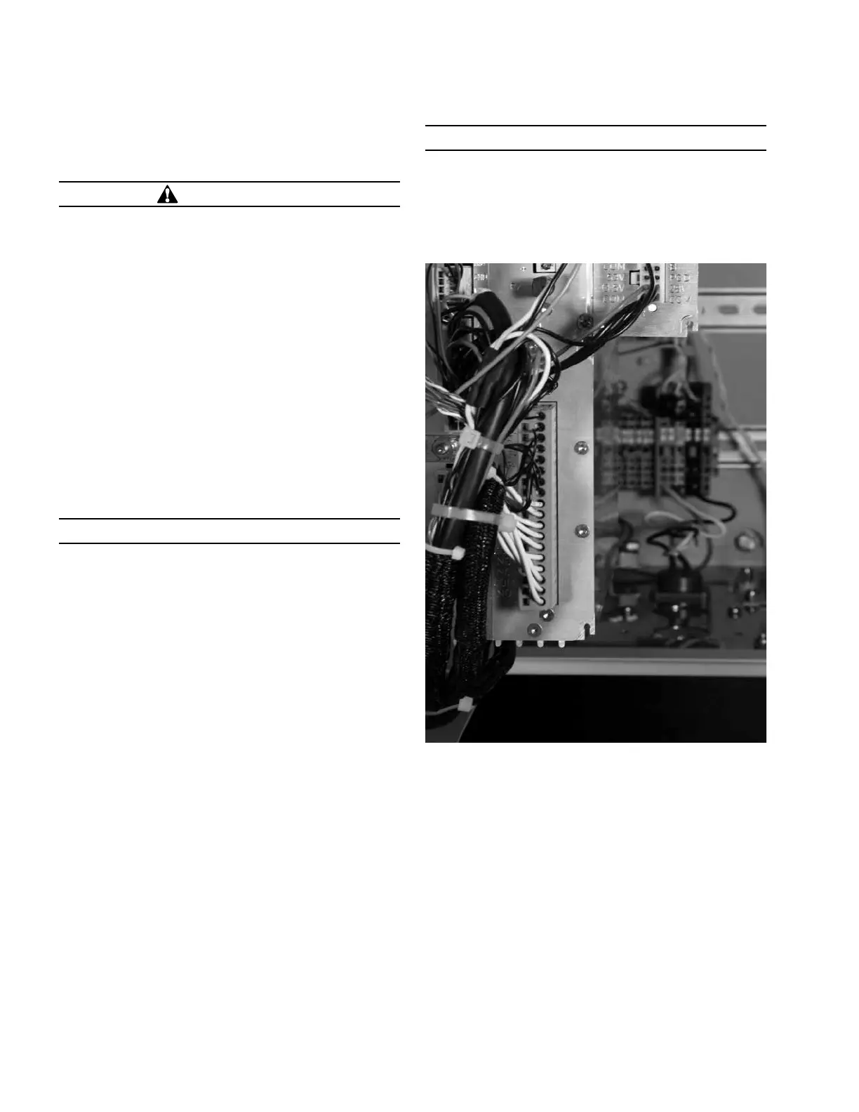
The Contact I/O module (Figure 19) permits connection of
contact-type input devices (switches, relays) and indicating
devices (relays, LEDs, lamps) to the Form 4D control to
effect local Contact input/output (I/O). The Contact I/O
module accessory is used for supplementing normal local
controls and status indicators for Contact I/O functions. The
first optional Contact I/O module inputs and outputs are
factory-set and are shown in Figure 20.
Additional I/O modules require customer configuration to
assign functionality for each contact input or output — via
the ProView NXG software configurable logic tool. Refer to
Service Information S280-104-2 Form 4D Microprocessor-
Based Recloser Control Programming Guide for additional
information.
IMPORTANT
The control gives priority to TCC timing and issuing a
trip signal rather than changing the status of a Contact
I/O module output or responding to a Contact I/O
module input. Refer to Table 4 for I/O response times.
The Contact I/O module for the first I/O card contains
four factory-set inputs and four outputs for Contact I/O
functions. Each Form 4D control can accommodate up to
four Contact I/O modules.
Whetting voltage is supplied from TB1 for the Contact I/O
inputs terminal block on the back panel as shown in Figure 20.
Two of the Contact I/O outputs are Form A relay contacts
and two are Form C relay contacts. All four outputs are of
non-latching type. Refer to Table 5 Output Ratings for output
fusing recommendations.
ote:N Latching is defined as an output that retains its
status when control power is removed.
Non-latching is defined as an output that returns to a
default status when control power is removed.
ote:N Following a firmware upgrade the Contact I/O
module output relays will revert to the de-energized
state. Additionally, the Contact I/O module may need
to be remapped.
NOTICE
External leads must be shielded and the shield must
be grounded at both ends. Terminate each lead with
a 320 VAC, 150 Joules metal oxide resistor (MOV), or
equivalent, at the remote end. Attach MOVs between
the leads and ground. Failure to properly shield and
protect leads can result in equipment damage and/or
unintentional operation.
Figure 19. Contact I/O Module
24 OPERATION INSTRUCTIONS MN280049EN September 2017
Form 4D Microprocessor-based pole-mount recloser control installation and operation instructions

 Loading...


