Reconnecting cable to apparatus bushings
Step 1
Determine that bushings are de-energized
•
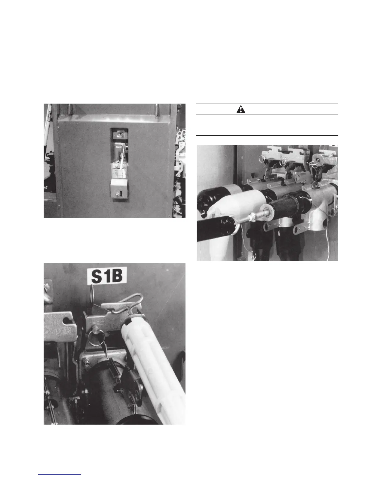
Check apparatus switch and see that it is open. Open
switch if it is closed. Refer to Figure 15.
•
Unthread hitch pin.
•
Engage catch strap in push plate slots with hotstick.
Refer to Figure 16.
•
Use hotstick to remove 200 A protective cap or arrester
from bushing adapter interface.
•
Insert test probe into bushing adapter using hotstick.
Refer to Figure 17.
•
Test for voltage by fuzzing or by using voltage detector
designed for connectors. Remove probe after testing.
Step 2
Connect cable to apparatus bushing
•
Grasp latch handle of PUSH-OP bushing adapter
(mounted on apparatus bushing) using hotstick and pull
backward until bushing adapter is completely unseated.
Remove bushing adapter by unhooking catch strap ring.
Place bushing adapter in clean protected area. Refer to
Figure 18.
Figure 16. Engage catch strap in push plate slots.
Figure 17. Test for voltage with test probe.
Figure 15. Open switch if it is closed.
WARNING
Hazardous Voltage. Do not proceed until cable is de-
energized. Failure to comply may result in death, severe
personal injury or equipment damage.
7600 A PUSH-oP DeADbreAk connector oPerAtion inStrUctionS MN650011EN May 2017

 Loading...


