Operation instructions
Equipment Required
•
One (1) Test Probe
•
Three (3) Grounding Elbows
•
Three (3) PUSH-OP Insulated Standoff Bushings
•
Three (3) PUSH-OP Bushing Adapters with Insulated
Protective Caps
•
One (1) Hotstick
•
One (1) Voltage Detector
•
Personal Protective Equipment
•
Insulating Rubber Blanket
•
Silicone Grease
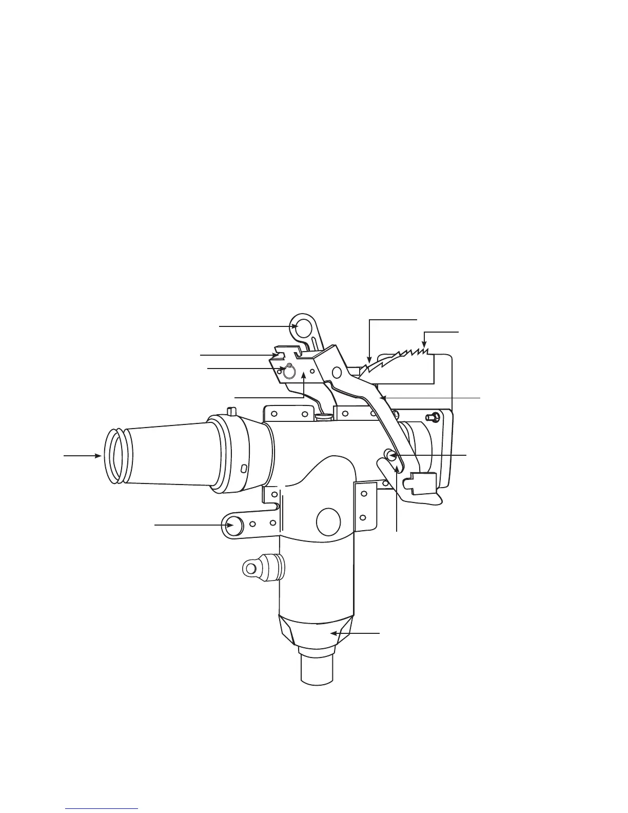
Figure 3. Line illustration of the PUSH-OP connector.
PUSH-OP CONNECTOR
OR PUSH-OP BUSHING
ADAPTER
OPERATING EYE
200 A
INTERFACE
LATCH HANDLE
PUSH PLATE SLOTS
HITCH PIN
PUSH PLATE
LOCKING SLOT
SHROUD PIN
BAIL BRACKET
LOCKING TEETH
FIRST NOTCHES
2 600 A PUSH-oP DeADbreAk connector oPerAtion inStrUctionS MN650011EN May 2017

 Loading...


