5KA369R, KA542R, AND KA57WE AUXILIARY SWITCH KIT INSTALLATION AND ADJUSTMENT INSTRUCTIONS MN280031EN
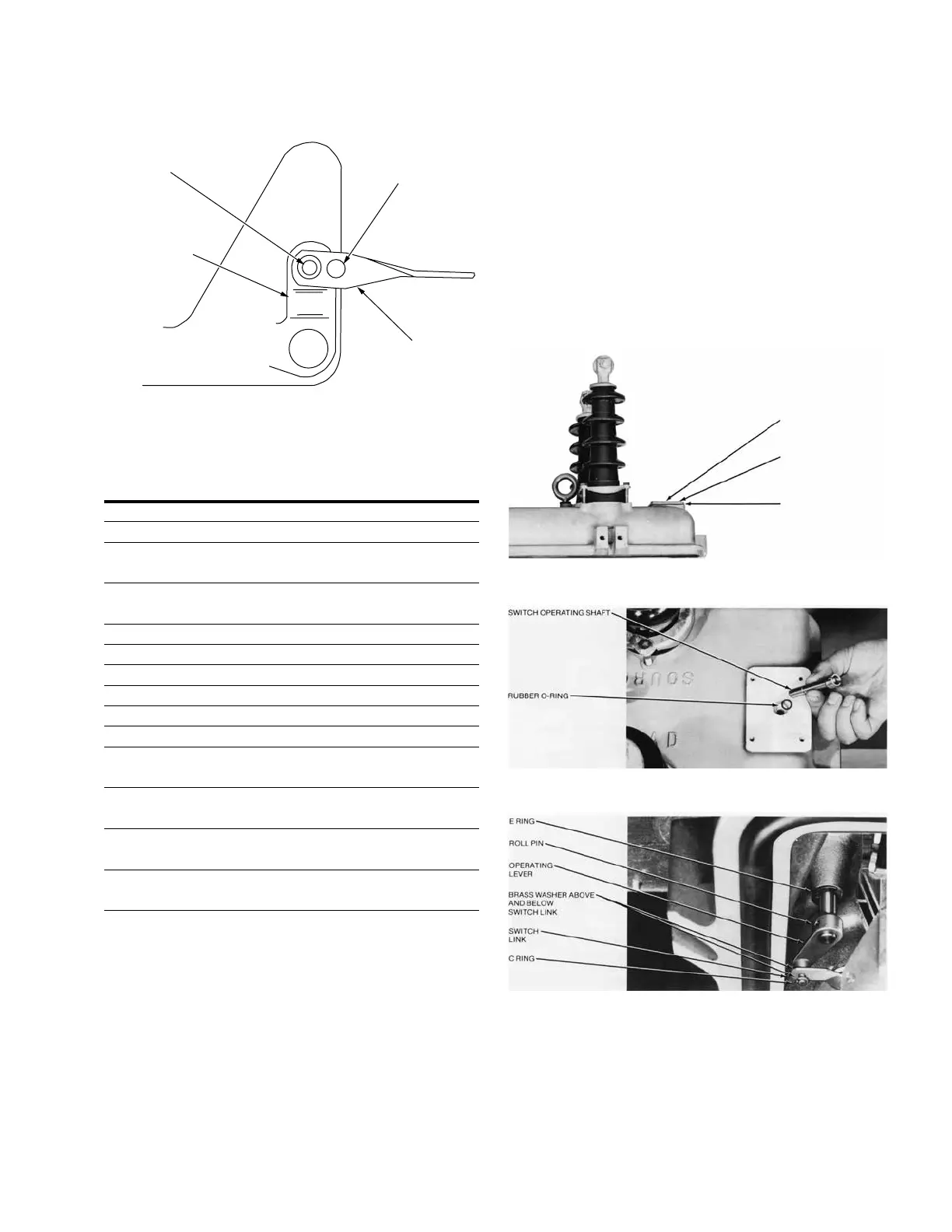
Hole "A"
Hole "B"
Switch
Link
Trip Link
on Recloser
Mechanism
Figure 6. Assemble switch link using hole “A” or hole
“B” per Table 2.
Table 2. Switch Link Hole Identification
Recloser Serial Number Hole “A” Hole “B”
R
Above 2732 X
RE
All X
RV
Below 1200 X
Above 1199 X
RVE
Below 600 X
Above 599 X
RX
All X
RXE
VW
All X
VWE
VWV
VWVE
W
Below 7334 X
Above 7333 X
WE
Below 6316 X
Above 6315 X
WV
Below 723 X
Above 722 X
WVE
Below 996 X
Above 995 X
6. Remove cover plate located at the end of head casting
opposite recloser operating handle by removing four
1/4-inch screws (Figure 7).
Gasket KP610R will be reused.
7. Place rubber o-ring in the recess in head casting.
Insert switch operating shaft through o-ring and hole
(Figure 8).
8. Lock operating shaft in place (Figure 9) using E-ring
(Item 4).
Fasten lever to operating shaft using roll pin.
Cover
1/4 inch screws
Gasket KP610R
Figure 7. Recloser head casting.
Figure 8. Switch operating shaft.
Figure 9. Linkage connection.

 Loading...


