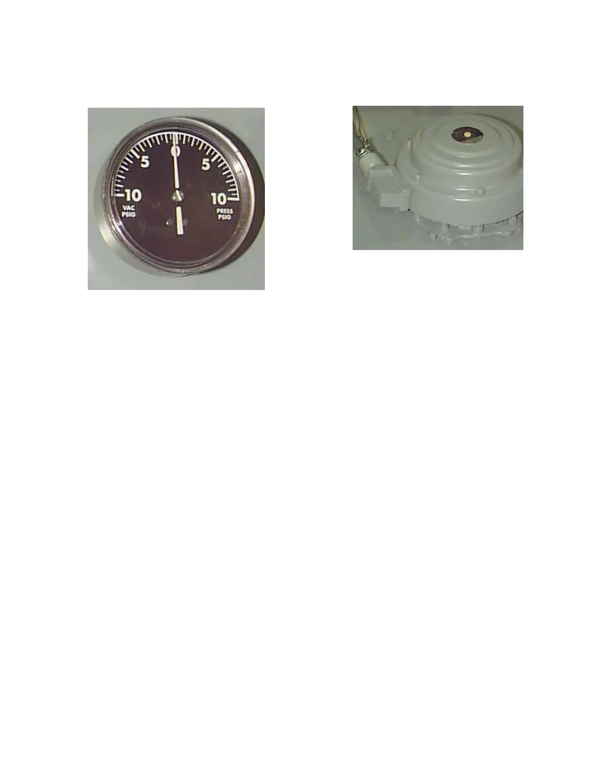
Pressure-vacuum gauge
The pressure-vacuum gauge indicates whether the gas
space in the tank is under positive or negative pressure.
The pressure will vary depending on the transformer
temperature. If the transformer is de-energized or operating
under light load in low ambients, the pressure may be
negative.
ote:N If the indicator reads zero and does not change
under any load condition, the transformer should be
checked for a possible leak in the seal.
If sufficient air has been absorbed by the liquid during
shipment or storage, the transformer may operate
indefinitely in the vacuum range, depending upon the
loading conditions. This, in itself, is not cause for concern,
provided the pressure vacuum gauge does not remain
on zero for any length of time an indication of a leak. The
transformer can safely operate in pressures ranging from -2
to +6 psig.
The unit may be equipped with pressure vacuum switches
with two SPDT contacts for remote alarm on positive and
negative pressure. For wiring and contact ratings, refer to
the schematic furnished with the transformer.
When required, the pressure gauge is furnished with a
pressure regulator that will automatically regulate the tank
pressure between 7.0 psig positive and 3.0 psig negative.
The pressure regulator is fitted with a valve and fitting to
take gas samples.
Pressure relief device
All substation transformers are furnished with a mechanical
pressure relief valve (PRV) or pressure relief device (PRD).
The cover-mounted PRD consists of a self-resetting, spring-
loaded diaphragm and a mechanical operation indicator.
Should the tank pressure increase above that for which the
device is set, the gas pressure will lift the diaphragm and
let the gas escape quickly. Immediately after the pressure
returns to normal, the diaphragm will reset and reseal the
transformer. A mechanical indicator will protrude vertically.
This must be reset manually to indicate subsequent
operations.
Contacts are optional. For wiring information, refer to the
schematic furnished with the transformer.
Figure 4. Pressure relief device.
Figure 3. Pressure-vacuum gauge.
5SubStation tranSformer inStallation and partS replacement information MN202002EN JUNE 2016
 Loading...