23
Instruction Book IB182071EN
July 2018
Remote Power Racking System
(RPR-2)
www.eaton.com
housing.
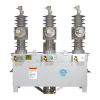
21) Align the RPR-2 and the Axial Compliant racking adapter with
the shaft on the racking adapter housing in the cell and connect
the two together. (Figure C.10)
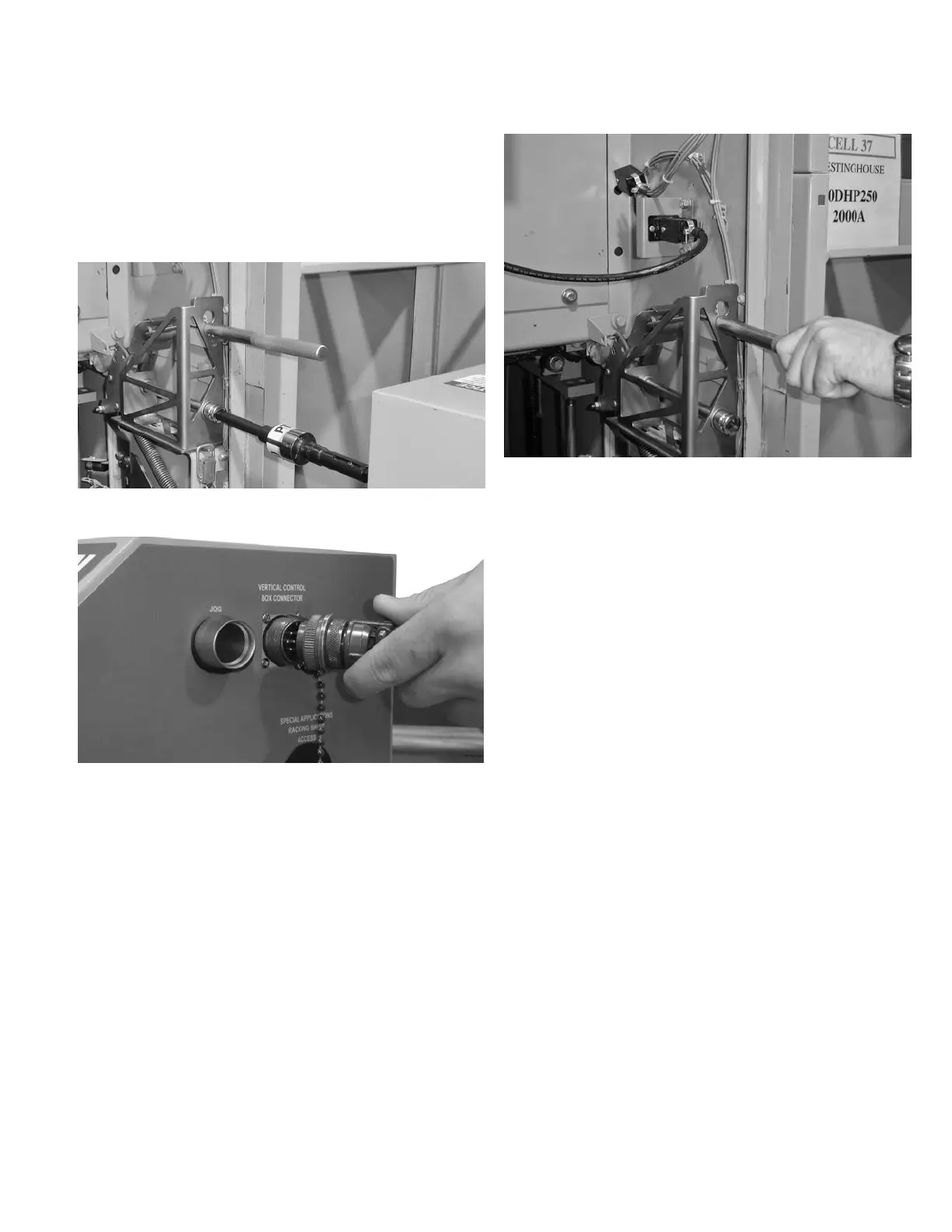
22) Connect the amphenol connector from the vertical control box
into the Vertical Control Box Connector located on the RPR-2.
(Figure C.11)
C.2 REMOVAL PROCEDURE USING THE RPR-2
1) Follow the same setup procedures as indicated in Steps
1 through 26 of Appendix C.1 for the insertion of the GE
Magneblast.
2) When the area is clear, depress and hold the remove button
(black with white arrow) on the pendant. (Figure 4.3) This will
initiate the removal process on the RPR-2 unit. The amber light
on the pendant and on the tower light will illuminate while the
power circuit breaker is in the removal process.
ote:N If at any time during the removal process the remove button is
released, the tower lights and pendant light will not be illuminated.
3) When the power circuit breaker is in the Remove position,
the green tower light will illuminate and the amber light on
the pendant will turn off. This indicates that it is now safe to
approach the power circuit breaker.
Figure C.10. Alignment of RPR-2 with Racking Adapter
Figure C.11. Attach Amphenol Connector
23) Pull back the “racking handle” in the racking adapter housing
and latch it to the housing. If needed adjust the handle to
ensure proper engagement of the clutch handle. (Figure C.12)
24) Once the clutch handle is pulled back and latched, the green
tower light will illuminate. If the breaker was inserted, the green
light will be off and no insertion racking will be allowed.
25) Engage the foot brake on the RPR-2 truck by stepping down
on the lever. (Figure 4.6) Verify that the correct power circuit
breaker program and the insert direction are selected by
viewing the LCD screen on the Fusion Controller. (Figure 4.1)
26) Take the Pendant and move a safe distance away from
front of the power circuit breaker. (The distance should be
predetermined through Arc-Flash calculations.)
27) When the area is clear, depress and hold the insert button
(white with black arrow) on the pendant. (Figure 4.3) This will
initiate the insertion process on the RPR-2 unit. The amber light
on the pendant and on the tower light will illuminate while the
power circuit breaker is in the insertion process.
ote:N If at any time during the insertion process the insert button is
released, the tower lights and pendant light will not be illuminated.
28) When the power circuit breaker is in the Connect position, the
red tower light will illuminate and the amber light on the pendant
will turn off. This indicates that it is now safe to approach the power
circuit breaker.
Figure C.12. Engaging The Clutch with the Racking Handle

 Loading...