16
Instructions for Installation, Operation and
Maintenance of Magnum SB Insulated Case
Low Voltage Power Circuit Breakers
EATON CORPORATION www.eaton.com
Instructional Leaet IB2C12063H03
Effective March 2012
Section 3: Circuit Breaker Description and
Operation
Introduction
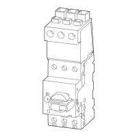
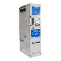
Magnum SB circuit breakers are available in both drawout and
fixed mounting configurations (Figures 17 and 18). A majority
of features are common to all configurations, and will be
discussed in this section. The mounting features unique to the
drawout and fixed configurations will be covered individually in
Sections 4 and 5 respectively.
Controls and indicators for both drawout and fixed circuit
breakers are functionally grouped on the front of the circuit
breaker. The front escutcheon (faceplate) is common for all
Magnum frame sizes up through 5000 amperes.
Double Wide frame circuit breakers utilize six (or eight) sets of
rear primary connections; these circuit breakers are available
from the factory with several different phase sequences,
distinguishable by the sixth character in the model number.
The phase sequence is also labeled on the rear of the circuit
breaker (Figure 19). For drawout breakers, phase sequence
labels are also supplied with the cassette and must be applied
by the switchgear builder. Circuit breakers with different phase
sequences are not interchangeable. Drawout breakers with
differing phase sequence are prevented from insertion into the
cassette by properly assembled rejection key plates (Refer to
“Rejection Interlocks” on page 11).
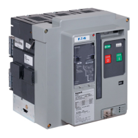
1. Baffled Arc Chute Cover
2. Secondary Disconnects (Contacts)
3. Faceplate (Front Cover)
4. Drawout Rail Supports
5. Integral Lifting Handle
6. Primary Disconnect Finger Cluster
7. Arc Chamber
8. Primary Vertical Adapter
9. Sensor Rating Viewing Window
10. Levering Device Bearing Plate
11. Padlockable Levering Device Access Door
12. Circuit Breaker Nameplate
Figure 17. Typical Drawout Circuit Breaker Features (Front and Rear Views)
 Loading...