55
Instructional Leaet IB2C12063H03
Effective March 2012
Instructions for Installation, Operation and
Maintenance of Magnum SB Insulated Case
Low Voltage Power Circuit Breakers
EATON CORPORATION www.eaton.com
Section 4: Drawout Circuit Breaker And
Cassette
General
Section 3 discussed topics and features common to all
Magnum SB circuit breakers, no matter what the mounting
configuration or type. In this section, features unique to
the drawout type circuit breaker and drawout cassette, not
covered elsewhere, are discussed. Drawings and dimensions
associated with all circuit breakers, drawout cassettes and
any appropriate primary bus connections can be found in a
separate document entitled Engineering Data TD01301004E.
The installation and levering of a drawout circuit breaker were
discussed in Section 2. If necessary, review that information,
since it will not be repeated here.
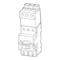
Figure 80. Drawout Circuit Breaker in Cassette
Drawout Cassette
A drawout circuit breaker is used in combination with a fixed
drawout cassette (Figures 80 and 82). The drawout circuit
breaker is equipped with automatic primary disconnects
(Figure 81). The cassette provides all of the necessary
interfaces to the drawout circuit breaker including automatic
primary and secondary connections. For the narrow frame
circuit breaker a single cassette style using horizontal stabs
and horizontal customer bus bar terminals is available (Figure
83). For the standard and double-wide circuit breakers three
cassette styles, all with vertical stabs, are available: basic,
standard, and universal. The standard cassette supplies vertical
stab/terminals only (Figure 85). The basic cassette omits the
copper stab/terminals so that these pieces can be integrated
with vertical bus bars provided by the switchgear builder
(Figure 84). The universal cassette provides a set of flat pad
terminals on the rear of the cassette that can be adapted to
vertical, horizontal or front connection (Figures 86). Mounting
locations for cell (TOC) switches, safety shutters, mechanical
interlocks and key interlocks are provided on the cassette.
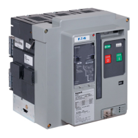
Figure 81. Drawout Circuit Breaker with Automatic Primary
Disconnects
 Loading...