34
SRM-250/250SI
E
N
G
L
I
S
H
D
E
U
T
S
C
H
I
T
A
L
I
A
N
O
ASSEMBLING
(LOOP HANDLE VERSION)
ZUSAMMENBAU
(RUNDGRIFF-VERSION [L-TYP])
ASSEMBLAGGIO
(VERSIONE CON IMPUGNATURA AD ANELLO)
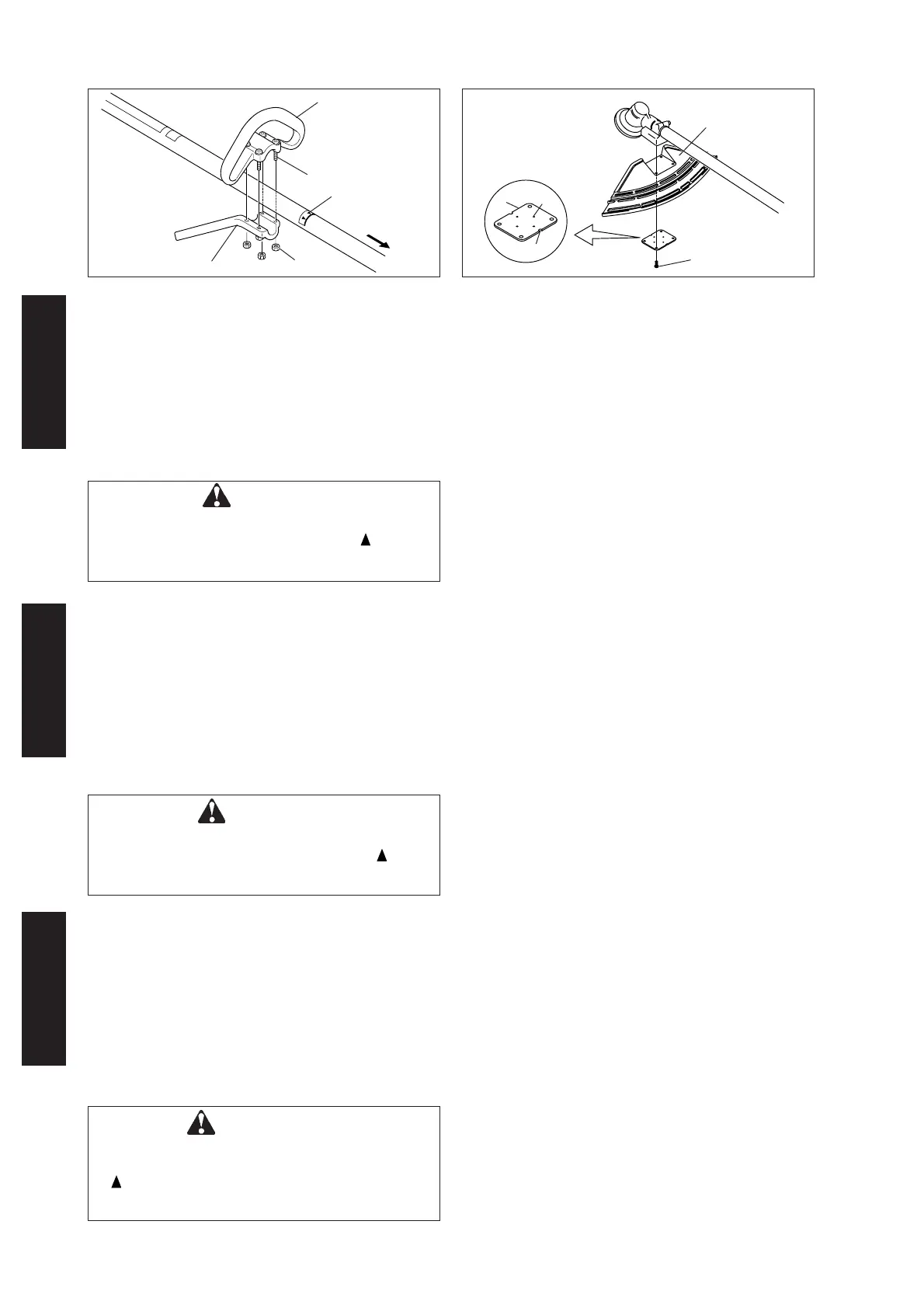
1. Loop handle
2. Screw M5×35
3. Loop handle bracket
LOOP HANDLE
Assemble loop handle and bracket to drive shaft assembly.
Position handle in comfortable operating position and
tighten screws (M5×35).
1. Linker Handgriff
2. Schraube M5×35
3. Befetigungsplatte
RUNDGRIFF VERSION (L-TYP)
Rundgriff und Halterung leicht an der Antriebswelle
befestigen.
Griff in einer bequemen Arbeitsstellung anbringen und die
Schrauben (M5×35) festziehen.
IMPUGNATURA AD ANELLO
Montare l’impugnatura e la staffa senza stringere
sull’albero motore.
Regolare l’impugnatura in una posizione di lavoro
confortevole e serrare le viti (M5×35).
1. Impugnatura anteriore
2. Vite M5×35
3. Supporto
3
4
5
1
INSTALLATION OF BRACKET
Fit bracket to mounting portion of angle transmission and
fix the bracket by holding fitting plate pressed from beneath
and tightening 4 bolts (M5×25) lightly.
1. Bracket
2. Bolt M5×25
3. Convex of fitting plate
Get notches and convexes of fitting plate to face
corresponding convexes and concaves of bracket, and fix
bracket tightening 4 bolts (M5×25) securely.
4. Fitting plate
5. Notch of fitting plate
ZUSAMMENBAU DES SCHUTZES
Befestigen Sie den Schutzhalter am Winkelgetriebe indem
Sie die Befestigungsplatte von unten dagegen drücken
und die 4 Schrauben (M5×25) leicht anziehen.
Bringen Sie die Kerbe und den Fixierpunkt der
Befestigungsplatte auf das entsprechende Gegenstück
des Schutzhalters und ziehen Sie die 4 Schrauben (M5×25)
fest.
1. Supporto
2. Bullone M5×25
3. Convesso della piastra
di raccordo
MONTAGGIO DEL SUPPORTO
Adattate il supporto alla parte di montaggio della testina e
fissate il supporto tenendo la piastra di raccordo premuta
verso il basso e stringendo le 4 bulloni (M5×25), ma non
troppo.
Fate combaciare gli incavi e i convessi della piastra di
raccordo in modo che convessi e concavi del supporto
corrispondano e fissate il supporto stringendo bene le 4
bulloni (M5×25).
4. Piastra di raccordo
5. Incavo della piastra
di raccordo
2
2
1
4
3
CAUTION
• Do not install the suspension point to be located
farther from you than the arrow mark (
).
• Install the handle so that it does not hide any of
the safety decals.
4. Nut
5. Arrow
6. To engine
5
6
4. Mutter
5. Pfeil
6. zum Motor
1. Schutzhalter
2. Schraube M5×25
3. Fixierungspunkt in der
Befestigungsplatte
4. Befestigungsplatte
5. Kerbe in der
Befestigungsplatte
4. Dado
5. Freccia
6. Al motore
VORSICHT
• Trageöse so montieren, dass diese nicht weiter
von Ihnen entfernt ist als die Pfeilmarke ( ).
• Handgriff so montieren, dass er die
Sicherheitsaufkleber nicht verdeckt.
ATTENZIONE
• Non installare l’attacco della cinghia per
collocarlo più lontano da te rispetto alla freccia
(
).
• Installare l’impugnatura in modo che non si
stacchi nessuna delle decalcomanie.
 Loading...