14
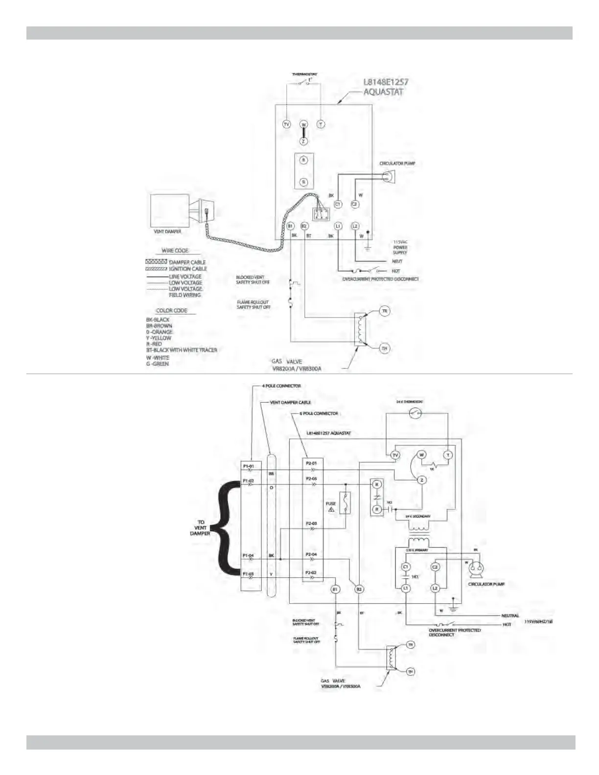
WIRING DIAGRAMS FOR HOT WATER BOILERS
STANDING PILOT
IF ANY OF THE ORIGINAL WIRE AS SUPPLIED WITH THIS APPLIANCE MUST BE REPLACED,
IT MUST BE REPLACED WITH TYPE 105°C THERMOPLASTIC WIRE OR ITS EQUIVALENT.
Note: S1A and S1B are the
automatic operation/hold damper
open switch. Switch is shown in
automatic position. S2, S3 and S4
are cam actuated snap switches.
Fuse blows fi rst time thermostat
closes after vent damper is plugged
in. After fuse blows L8148E1257 will
operate burners only if vent damper
is connected (plugged in).
 Loading...