25
GB
2. SYMBOLS AND SAFETY WARNINGS (Fig.25)
1 - Read operator’s instruction book before
operating this machine.
2 - Wear head, eye and ear protection.
3 - Wear strong boots and gloves when cutting
with metal or plastic blades.
4 - Be aware that objects can be thrown.
5 - Keep bystanders away 15 m.
6 - Do not use the brushcutter with the wood
cutting disk.
7 - Warning! Kickback it’s danger.
8 - On machines with a bent drive shaft it is not
possible to t disks, only line heads.
9 - Type of machine: BRUSH CUTTER.
10 - Guaranteed sound power level.
11 - CE conformity marking.
12 - Serial number.
13 - Year of manufacture.
14 - Max. speed of output shaft, RPM.
15 - Primer bulb.
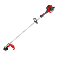
3. MAIN COMPONENTS (Fig.1)
4 - Harness
5 - Bevel gear
6 - Curved guard
7 - Nylon line head
8 - Fuel tank cap
9 - Purge Bulb
10 - Carburettor adjustment screws
11 - Muer guard
12 - Spark plug
13 - Air lter
14 - Starter Handle
15 - Choke Lever
16 - Throttle trigger lockout
17 - STOP button
18 - Throttle lever
19 - Harness attachment
20 - Handle
21 - Shaft arm
22 - DS 2400 D attachments coupling
4. ASSEMBLY
FITTING THE NYLON LINE HEAD (Fig. 8)
Put the upper (F) ange in place. Put the head xing
pin (H) in the appropriate hole (L) and tighten the
head (N) anti-clockwise by hand.
FITTING THE HANDLE (Figs. 2)
Fit the handle onto the shaft arm and secure it
using screws (A). The handle position is calculated
depending on the requirements of the operator.
ASSEMBLING THE SAFETY BOOM (Fig. 9A)
When using the disc instead of nylon line head, it
is necessary to set up the “safety boom”. Fix the
boom (A) under the attachment (C) of handle (20B,
Fig. 1) by means of the screws (B). Taking care to
verify the “safety boom” being on the left side of
the brushcutter.
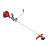
Assembling the bike handle
DS 2200 T (Figs. 4)
- Place the bike handle (A, Fig.4) in the lower hub
(B1).
CAUTION: The bike handle (A) must be
xed onto the hub (B) inside the two notches
(C) indicated on the bike handle.
- Place the upper hub (B2) in position and tighten
the 4 screws (D), without nally tighten yet.
- Line up the handlebar at a right angle to the
drive tube.
- Tighten down the screws (D) rmly.
DS 2400 T (swivelling bike handle)
- Release the wing screw (E, Fig.5) and unscrew
it until the bike handle (F) can be turned anti-
clockwise.
- Turn the handlebar 90° and then swing the
handles up.
- Tighten down the wing screw (E) rmly.
Storage or transportation positions
- Reverse the sequence described above to
swing the handles up and turn the bike handle
clockwise.
Mounting the control handles (DS 2200 T –
DS 2400 T) (Figs. 6)
- Loosen the screw (G, Fig.6). The nut (H) remains
in the control handle (L).
- Push the control handle (L) (throttle trigger M
must point toward the gearbox) onto the bike
handle (N) so that the holes (P) line up.
 Loading...