02/2011 - Art. Nr. 4200 1029 5200B2
Overview
Contents
We accept no responsibility for damage
arising from:
- inappropriate use.
- incorrect installation and/or repair on the
part of the buyer or any third party,
including the fitting of non-original parts.
Final delivery and instructions for use
The firing system fitter must supply the
operator of the system with operating and
maintenance instructions on or before final
delivery. These instructions should be
displayed in a prominent location at the point
of installation of the heat generator, They
should include the address and telephone
number of the nearest customer service
centre.
Notes for the operator
The system should be inspected by a
specialist at least once a year. Depending on
the type of installation, shorter maintenance
intervals may be necessary! It is advisable to
take out a maintenance contract to guarantee
regular servicing.
Declaration of conformity
for gas burners
We, certified company No. AQF030,
F-74106 ANNEMASSE Cedex,
declare under our sole responsibility
that the products
VG 2.120 D
VG 2.160 D
VG 2.210 D
conform to the following standards
EN 50165
EN 55014
EN 60335-1
EN 60335-2-102
EN 60555-2
EN 60555-3
EN 676
Belgian royal decree dated 08/01/2004
These products bear the CE mark in
accordance with the stipulations of the
following directives
2006/ 42/EC Machinery directive
2004/108/EC EMC directive
2006/ 95/EC Low voltage directive
92/ 42/EEC EEC Working
efficiency directive
Annemasse, 25th March 2010
M. SPONZA
Important information
VG 2.120/160/210 D burners are designed
for the low-pollutant combustion of natural
gas and propane gas. The design and
function of the burners meet standard EN
676. They are suitable for use with all heat
generators complying with standard EN 303
or for use by hot air generators complying
with standard DIN 4794 or DIN 30697 within
their respective performance range. Any
other type of application requires the
approval of ELCO.
Installation, commissioning and maintenance
must only be carried out by authorised
specialists and all applicable directives and
regulations must be complied with.
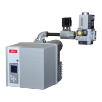
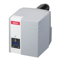
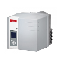
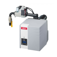
Burner description
VG 2.120/160/210 D burners are two-stage
fully automatic monoblock devices. The
special design of the combustion head
enables combustion with low levels of
nitrogen oxide and increased output. Class 3
type-approval in accordance with EN676
certifies that the lowest emission values have
been achieved and means that the national
environmental regulations have been met
AT: KFA 1995, FAV 1997
CH: LRV 2005
DE: 1.BImSChV
Emissions values may differ, depending on
combustion chamber dimensions,
combustion chamber load and the firing
system (three-pass boilers, boilers with
reverse firing). For specifying warranty
values, the conditions for the measuring
equipment, tolerances and humidity must be
observed.
Packaging
The burner packaging also contains:
1 Gas connection flange
1 Compact gas train with gas filter
1 Burner flange
with insulation
1 Bag containing mounting parts
1 Bag containing Technical
Documentation
The following standards should be observed
in order to ensure safe, environmentally
sound and energy-efficient operation:
EN 226
Connection of fuel oil and forced-draught gas
burners to a heat generator
EN 60335-1, -2-102
Specification for safety of household and
similar electrical appliances, particular
requirements for gas burning appliances
Gas lines
When installing the gas lines and trains, the
general directives and guidelines, as well as
the following national regulations, must be
observed:
CH: - G1 instruction text from SSIGE
- EKAS form no. 1942,
liquefied gas directive, part 2
- Cantonal authority guidelines (e.g.
directives for the pilot valve)
DE: - DVGW-TVR/TRGI
Installation location
The burner must not be used in rooms with
aggressive vapours (e.g. hair spray,
tetrachloroethylene, carbon tetrachloride),
high levels of dust or high air humidity (e.g.
laundry rooms).
If no connection to an air exhaust system is
provided for the air supply, there must be a
supply air inlet measuring:
DE: up to 50 kW: 150 cm
2
per additional kW: : + 2.0 cm
2
CH: QF [kW] x 6= ...cm
2
; but at least
150 cm
2
.
Variations may arise as a result of local
regulations.
Overview Contents.................................................................... 2
Important information ................................................ 2
Burner description..................................................... 3
Operation Operation, safety operation....................................... 4
Automatic combustion control unit ......................... 5-7
Terminal allocation chart, connection socket .........8-9
MB-ZRDLE gas train............................................... 10
Assembly Burner assembly, gas train assembly ............... 11-12
Checking/setting the mixing unit ............................. 12
Electrical/gas connection ........................................ 13
Testing before start up ............................................ 13
Commissioning Adjustment data ..................................................... 14
Air regulation........................................................... 15
Setting the MB-ZRDLE gas train............................. 16
Pre-adjustment without flame ...........................17-18
Setting the flame ................................................ 19-21
Saving the adjustment values in the display .......... 22
Servicing Maintenance ..................................................... 23-24
Troubleshooting ................................................. 25-26
Fault diagnosis menu,
Operating statistics menu .................................. 27-28
 Loading...