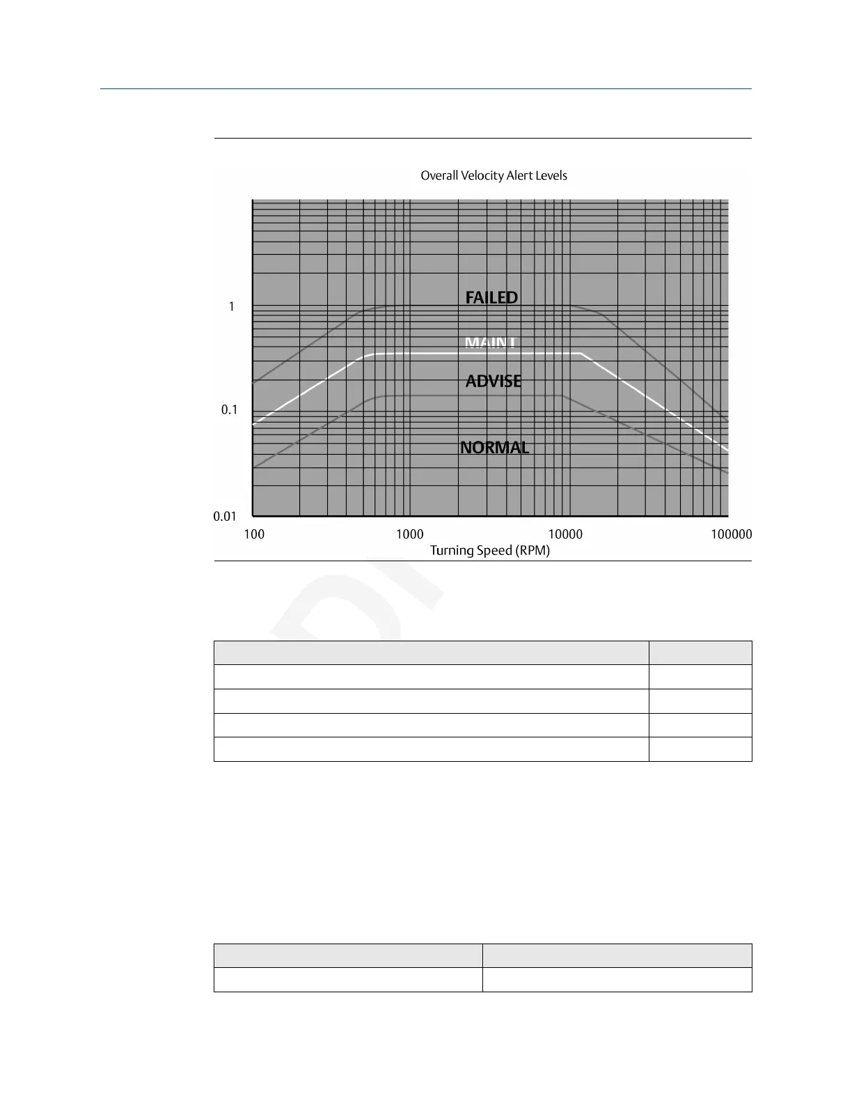
Figure 5-3: General fault levels
Depending on the type of machine being monitored, the values shown in this graph
should be multiplied by the service factors given in Table 5-1.
Table 5-1: Service factor multiplier
Machinery type Service factor
Single-stage Centrifugal Pump, Electric Motors, Fans 1.0
Non-critical Chemical Processing Equipment 1.0
Turbine, Turbine Generator, Centrifugal Compressor 1.6
Miscellaneous Equipment 2.0
Figure 5-3 shows the Overall Velocity thresholds for root-mean-square (RMS) velocity in
units of inches per second. Particularly, in digital acquisition systems, it is customary to
measure and calculate with RMS quantities. While it is accepted practice in the industry to
convert between RMS and peak values using the 1.4142 conversion factor, it is not
technically correct to do so except for a pure sinusoidal waveform. For this reason, the
AMS Wireless Vibration Monitor measures, calculates, and reports Overall Velocity in RMS,
and it is necessary to multiply by 1.4142 to get the corresponding peak levels if this is the
preferred format.
Table 5-2: Default velocity levels in AMS Wireless Vibration Monitor
Alert level Velocity (in RMS)
Advise 0.14 in/s
User Guide Overall Velocity, PeakVue, and temperature
MHM-97927-PBF July 2020
MHM-97927-PBF, DRAFT 55

 Loading...


