10
EN Drive Installation Manual
Electrical Installation
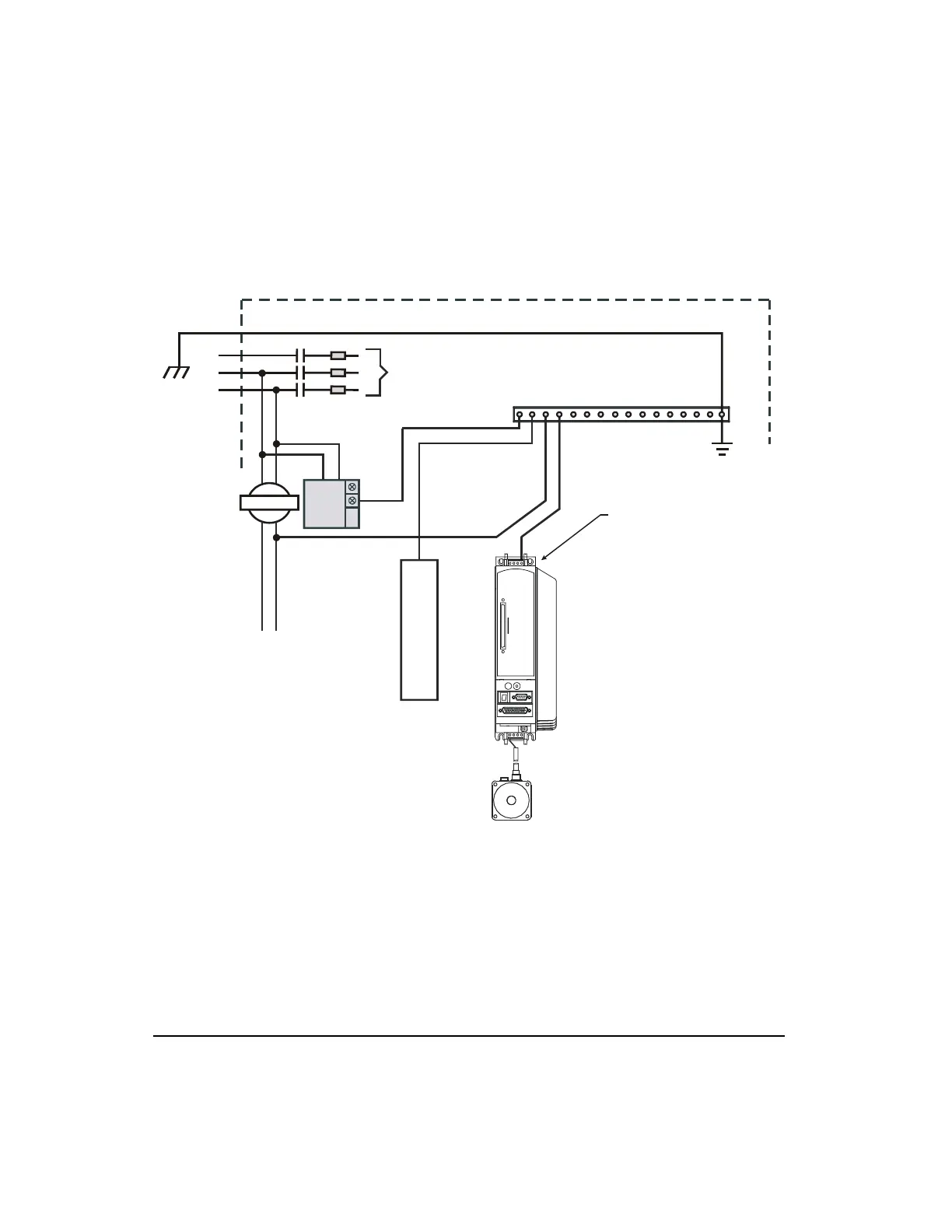
System Grounding
Figure 5: Typical System Grounding Diagram
Power Supply Requirements
The examples below show AC power connections for single phase and three phase drives.
These examples are shown for reference only. Local electrical codes should be consulted
before installation.
AC Filter
NT or MG Motor
Paint must be removed
from mounting surface
to assure the chassis
of the drive is connected
to the single point
ground.
DC
Power Supply
Enclosure Wall
Mains Contactor
AC Line Fuses
3 Phase
Line
Power
+24 VDC
User
Supply
+
-
+
N
Paint
must be
removed
at least
from
behind
the
mounting
tab
Single Point Ground
Ground connection rail and enclosure panel should
have a low impedance connection. Paint must be
removed from panel mounting surface.
Ground
L1
L2
L3
Control
Voltage
Transformer
PE
Artisan Technology Group - Quality Instrumentation ... Guaranteed | (888) 88-SOURCE | www.artisantg.com
 Loading...