Operating instruction
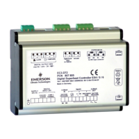
EC3-X33 Superheat Controller and ECD-002
Keypad / Display Unit
Emerson Climate Technologies GmbH www.emersonclimate.eu
Am Borsigturm 31 I 13507 Berlin I Germany Date: 03.04.2017 EC3-X33_OI_ML_R12_865009.docx
General information:
EC3-X33 is a universal superheat controller in conjunction with EMERSON
Electrical Control Valves EX4...EX8 and FX5…FX9.
Note: This document contains short form instructions for experienced users.
Safety instructions:
• Read operating instructions thoroughly. Failure to comply can result in
device failure, system damage or personal injury.
• According to EN 13313 it is intended for use by persons having the
appropriate knowledge and skill.
• Do not exceed the specified maximum ratings for pressure, temperature,
voltage and current.
• Before installation or service disconnect all voltages from system and device.
• Do not operate system before all cable connections are completed.
• Entire electrical connections have to comply with local regulations.
Note: The EC3-X33 series contains a VRLA battery = valve regulated rechargeable
lead-acid battery. The battery must NOT be disposed of with other commercial
waste. Instead, it is the user’s responsibility to pass it to a designated collection
point for the safe recycling of batteries (harmonized directive 2012/19/EU). For
further information contact your local environmental recycling center.
Mounting position:
The EC3-X33 is designed to be mounted onto a standard DIN rail. Mounting
position: on vertical walls, with stepper motor connector on top side only.
Mounting of ECD-002:
• ECD-002 can be installed at any time also during operation.
• ECD-002 can be mounted in panels with
71x29 mm cutout.
• Push controller into panel cut-out.(1)
• Make sure that mounting lugs are flush with
outside of controller housing
• Insert Allen key into front panel holes and turn
clockwise. Mounting lugs will turn and gradually
move towards panel (2)
•
Turn Allen key until mounting lug barely touches
panel. Then move other mounting lug to the same
position (3)
• Tighten both sides very carefully until keypad is
secured. Do not over tighten as mounting lugs
Electrical Installation:
• Refer to the electrical wiring diagram for electrical connections.
• Do not apply voltage to the controller before completion of wiring.
• Ground the metal housing with a 6.3 mm spade connector.
• Keep controller and sensor wiring well separated from mains wiring. Minimum
recommended distance 30 mm.
• Use a class II category transformer for 24 VAC power supply. Do not ground the
24 VAC lines. We recommend using individual transformers for EC3
controller(s) and for 3
rd
party controllers to avoid possible interference or
grounding problems in the power supply.
• Connecting any EC3 inputs to mains voltage will permanently damage the EC3.
• The use of the relay is essential to protect the system in case of power failure if
the communications interface or the ECD-002 are not utilized.
• If the output relay is not utilized, the user must ensure appropriate safety pre-
cautions are in place to protect the system against damage caused by a power
failure.
• In order to provide system protection in the event of power loss, it is
recommended to change the battery annually.
Digital input status is dependent to operation of compressor/thermostat
Demand (compressor must be ON)
Wiring:
A: White wire B: Black wire C: Blue wire D: Brown wire
E: Plug cable assembly EXV-Mxx for connection to EX4…EX8 and FX5…FX9
G: Remote control panel, system controller
H: Alarm relay, dry contact. Relay coil is not energized at alarm or power off.
I: Digital input (0V/open = Stop; 24V/closed = Start)
J: Transformer Class II, 24 VAC secondary / 25 VA
K: Third party controller (can use the analog output signal from EC3)
Preparation for Start-up:
• Vacuum the entire refrigeration system
• Note: EMERSON Electrical Control Valves EX4…EX8 and FX5…FX9 are
delivered at half open position. Do not charge system before closure of valve.
• Apply supply voltage 24 V to EC3 while the digital input is 0 V (open). The
valve will be driven to close position.
• After closure of valve, start to charge the system with refrigerant.
• Start the system and check the superheat and operating conditions.