Operating instruction
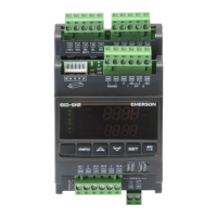
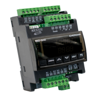
EXD-HP1/2 Controller with ModBus
communication capability
Emerson Climate Technologies GmbH www.climate.emerson.com/en-gb Date: 17.12.2020
Am Borsigturm 31 I 13507 Berlin I Germany EXD-HP12_OI_EN_DE_RU_1220_R06_865921.docx
General information:
EXD-HP1/2 are stand-alone superheat and or economizer controllers. EXD-HP1 is
intended for operation of one EXM/EXL or EXN valve whereas EXD-HP2 is
designed for operation of two independent EXM/EXL or two EXN valves.
Note: It is possible to use only circuit 1 from EXD-HP2. In this case, the circuit
2 must be disabled (C2 parameter) and the sensors and the valve for the second
circuit are not needed.
ModBus communication is described in a Technical Bulletin and it is not covered
by this document.
Technical Data:
EXD-HP1: 15VA EXD-HP2: 20VA
Removable screw terminals wire size 0.14...1.5 mm
2
Potential free contacts (free from voltage)
Operating/surrounding temp.
SPDT contact 24V AC 1 Amp inductive load;
24V AC/DC 4 Amp resistive load
During normal operation (no alarm condition)
Deactivated/de-energized:
During alarm condition or power supply is OFF
Stepper motor output
Coil: EXM-125/EXL-125 or EXN-125
Valves: EXM/EXL-… or EXN-…
Marking
Warning -Flammable refrigerants:
EXD-HP1/2 has a potential ignition source and does not comply with ATEX
requirements. Installation only in non-explosive environment. For flammable
refrigerants only use valves and accessories approved for it!
Safety instructions:
• Read operating instructions thoroughly. Failure to comply can result in device
failure, system damage or personal injury.
• It is intended for use by persons having the appropriate knowledge and skill.
• Before installation or service disconnect all voltages from system and device.
• Do not operate system before all cable connections are completed.
• Do not apply voltage to the controller before completion of wiring.
• Entire electrical connections have to comply with local regulations.
• Inputs are not isolated, potential free contacts needed to be used.
• Disposal: Electrical and electronic waste must NOT be disposed of with other
commercial waste. Instead, it is the user responsibility to pass it to a designated
collection point for the safe recycling of Waste Electrical and Electronic
Equipment (WEEE directive 2019/19/EU). For further information, contact
your local environmental recycling center.
Electrical connection and wiring:
• Refer to the electrical wiring diagram for electrical connections.
• Note: Keep controller and sensor wiring well separated from supply power
cables. Minimum recommended distance 30mm.
• EXM-125, EXL-125 or EXN-125 coils are supplied with fix cable and JST terminal
block at cable end. Cut the wires close to terminal block. Remove the wire
insulation approximately 7 mm at the end. It is recommended that the wires end to
be equipped with core cable ends or metallic protective sleeve. When connecting
the wires of EXM/EXL or EXN, consider the color coding as follows:
7 BL
8 OR
9 YE
Blue
Orange
Yellow
Blue
Orange
Yellow
31 BL
32 OR
33 YE
Blue
Orange
Yellow
Blue
Orange
Yellow
• The digital input DI1 (EXD-HP1) and DI1/D12 (EXD-HP1/2) are the
interfaces between EXD-HP1/2 and upper level system controller if the
Modbus communication has not been used. The external digital shall be
operated in function system’s compressor/demand.
• If the output relays are not utilized, the user must ensure appropriate safety
precautions are in place to protect the system.
Note: Connecting any EXD-HP1/2 inputs to the supply voltage will
permanently damage the EXD-HP1/2.
Wiring base board (EXD-HP1/2) :
Note:
• Base board is for function of superheat control or Economizer control.
• Alarm relay, dry contact. Relay coil is not energized during alarm condition or
power off.
• Hot gas discharge sensor input is mandatory only for economizer control function.
Warning: Use a class II category transformer for 24VAC power supply. Do
not ground the 24VAC lines. We recommend using individual transformers for
EXD-HP1/2 controller and for third party controllers to avoid possible
interference or grounding problems in the power supply.