Instruction Manual Supplement
D104490X012
DVC6200 Digital Valve Controller
January 2020
5
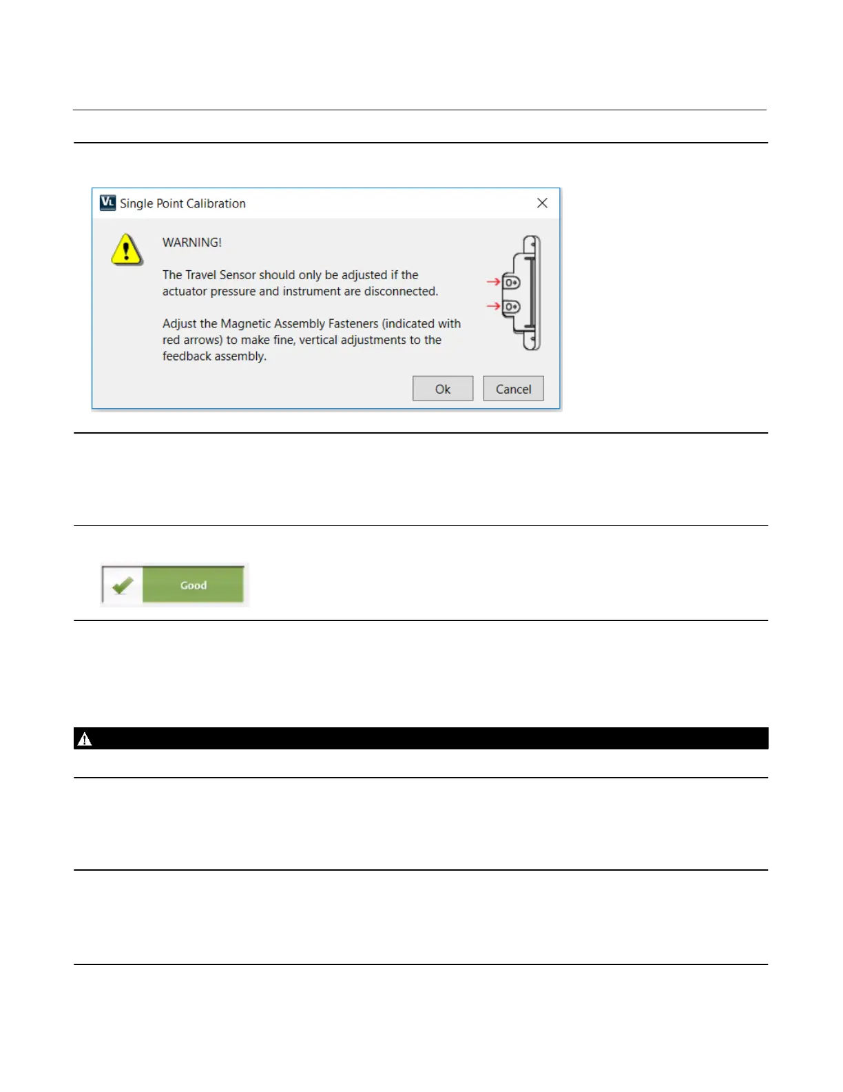
Figure 1. Warning Screen
4.7 On the Travel Screen, enter the Actual Travel (in) and Observed Travel (%). Then click Next.
4.7a Read the alignment recommendations in the bottom left hand corner of the screen. Follow the alignment
recommendations, to move the feedback assembly up or down, until the alignment is indicated with the
good status symbol (Figure 2). Then click Next to put your digital valve controller back In Service.
Figure 2. Good Status Symbol
4.8 Review the travel setpoint and measured travel on the Control Signal Screen. Adjust the travel setpoint to match
travel. This will minimize valve movement when air is resupplied. Once the travel setpoint matches travel, click
Next.
4.9 Reintroduce instrument air pressure to the digital valve controller. The air pressure supplied will be shown on the
dial graphic on the Air Screen. Once you’ve confirmed instrument air has been supplied, click Next.
WARNING
Refer to the Installation Warning on page 2.
4.10 On the resulting Finish Screen adjust the Travel Setpoint to remove force on the valve locking mechanism. Then
carefully remove the valve locking mechanism.
Note
The lack of a full travel calibration can impact the accuracy of the position feedback. While this does not impact the instrument’s
ability to control the process, it can influence the results of diagnostic tests.
This calibration is approximate and accuracy is limited. To ensure optimal accuracy and operation, perform an auto travel
calibration on the digital valve controller as soon as conditions allow.

 Loading...


