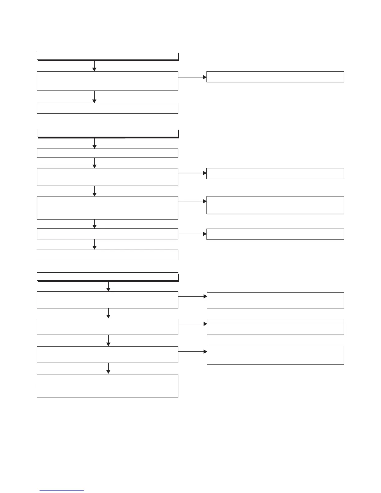
8-4 FL11.4ATR
[Video Signal Section]
No
Is the "L" pulse sent out Pin(1) terminal of remote
control receiver (RS4051
) when the infrared remote
control is activated?
Ye s
Is the "L" pulse supplied to Pin(2) of CN4052?
Ye s
Is approximately +3.3V voltage supplied to Pin(3)
terminal of the remote control receiver (RS4051)?
No
FLOW CHART NO.2
Operation is pos
sible from the unit.
Check AL+3.3V line and service it if defective.
No
Replace the IR Sensor CBA Unit
or the remote control unit.
Replace the IR Sensor CBA Unit.
Ye s
Replace Digital Main CBA Unit.
When pressing each switches (SW4001~SW4007)
do the voltage of Pin(2) of CN4001 decrease?
The key operation is not functioning.
FLOW CHART NO.1
Ye s
Replace Digital Main CBA Unit.
Replace the Function CBA Unit.
No
No operation is possible from the remote control unit.
Picture does not appear normally.
FLOW CHART NO.3
Is approximately +24V voltage supplied to Pin(13, 14)
of CN632?
Is
approximately +
24V voltage supplied to Pin(16, 17) of
CN632?
CL3005, Digital Main CBA Unit or LCD Module
Assembly may be defective.
Check and replace these parts.
No
No
Ye s
Is approximately +5.7V voltage supp
lied to Pin(11) of
CN632?
See FLOW CHART NO.9 <AL+5V is not output.
[Power Supply Section]>
See FLOW CHART NO.5 <P-ON+24V is not output.
[Power Supply Section]>
See FLOW CHART NO.8 <AMP+24V is not output.
[Power Supply Section]>
No
Ye s
Ye s
 Loading...