EasyManua.ls Logo

Emerson ROSEMOUNT 5081-A User Manual

Emerson ROSEMOUNT 5081-A
128 pages
To Next Page IconTo Next Page
To Previous Page IconTo Previous Page
Page #103 background imageLoading...
Page #103 background image

!#  '(#"
(&#) '##("
'(#"
(&#) '##("
 +&"") ("&&#&!'''
 (&#) '##("+"+&""#&) (!''''#+"
 (!$&()&!')&!"(" &(#"$&# !'
 #,-"!')&!"(" &(#"$&# !'
 & #&"!')&!"(" &(#"$&# !'
 (#(  #&"!')&!"(" &(#"$&# !'
 #.#"!')&!"(" &(#"$&# !'
 ?!')&!"(" &(#"$&# !'
 '!) (""$)()&&"('''# *#,-"
 '!) (""$)()&&"(' #&""#.#"
 '!) (""$)('?
 '!) ("(!$&()&
 !')&"&&"*# (
+&"") ("&&#&!'''
0?<)F;<CKI8EJD@KK<I:FEK@ELFLJCPDFE@KFIJK?<J<EJFI8E;KI8EJD@KK<I=FI:FE;@K@FEJK?8K:8LJ<<IIFE<FLJD<8J
LI<D<EKJ3?<E8GIF9C<DF::LIJK?<KI8EJD@KK<I;@JGC8PJ<@K?<I8N8IE@E>FI=8LCKD<JJ8><N8IE@E>8C<IKJK?<LJ<I
K?8K8GFK<EK@8CCP;@J89C@E>:FE;@K@FE<O@JKJ0?<I<@J8?@>?GIF989@C@KPK?8KK?<D<8JLI<D<EK@J@E<IIFI=8LCK8C<IKJK?<
LJ<IK?8K8;@J89C@E>:FE;@K@FE<O@JKJ%=8=8LCKD<JJ8><@JJ?FN@E>8CCD<8JLI<D<EKJJ?FLC;9<I<>8I;<;8J<IIFE<FLJ
+74=0+&""2>=38C8>=4G8BCB
 0?<D8@E;@JGC8PI<D8@EJJK89C<@K;F<JEFK=C8J?
 N8IE@E>D<JJ8><8GG<8IJ8CK<IE8K<CPN@K?K?<K<DG<I8KLI<8E;FLKGLKI<8;@E>J@EK?<J<:FE;C@E<F=K?<;@JGC8P/<<
/<:K@FE=FI8E<OGC8E8K@FEF=K?<N8IE@E>D<JJ8><J8E;JL>><JK<;N8PJF=:FII<:K@E>K?<GIF9C<D
+74=0) (4G8BCB
 0?<D8@E;@JGC8P=C8J?<J
 0?<NFI;J"1(08E;$+( 8GG<8I@EK?<D8@E;@JGC8P
 =8LCKD<JJ8><8GG<8IJ8CK<IE8K<CPN@K?K?<K<DG<I8KLI<8E;FLKGLKI<8;@E>J@EK?<J<:FE;C@E<F=K?<;@JGC8P/<<
/<:K@FE=FI8E<OGC8E8K@FEF=K?<=8LCKD<JJ8><J8E;JL>><JK<;N8PJF=:FII<:K@E>K?<GIF9C<D
 0?<FLKGLK:LII<EKN@CCI<D8@E8KK?<GI<J<EKM8CL<FI>FKFK?<GIF>I8DD<;=8LCKM8CL</<</<:K@FE=FI;<K8@CJFE
?FNKFGIF>I8DK?<:LII<EK><E<I8K<;;LI@E>8=8LCK:FE;@K@FE
 %=K?<KI8EJD@KK<I@J@E$+( N?<EK?<=8LCKF::LIJK?<FLKGLKI<D8@EJ8KK?<GIF>I8DD<;?FC;M8CL<0F8C<IKK?<LJ<I
K?8K8=8LCK<O@JKJK?<NFI;"1(08GG<8IJ@EK?<D8@E;@JGC8P8E;K?<;@JGC8P=C8J?<J=8LCKFI;@8>EFJK@:D<JJ8><
8CJF8GG<8IJ
 %=K?<KI8EJD@KK<I@JJ@DLC8K@E>8EFLKGLK:LII<EKN?<EK?<=8LCKF::LIJK?<KI8EJD@KK<I:FEK@EL<JKF><E<I8K<K?<J@D
LC8K<;:LII<EK0F8C<IKK?<LJ<IK?8K8=8LCK<O@JKJK?<NFI;"1(08GG<8IJ@EK?<;@JGC8P8E;K?<;@JGC8P=C8J?<J
+74=0=&&#&4G8BCB
 0?<D8@E;@JGC8PI<D8@EJJK89C<@K;F<JEFK=C8J?
 ;<J:I@GK@FEF=K?<<IIFI8GG<8IJ!IIFID<JJ8><JKPG@:8CCP8GG<8I;LI@E>:8C@9I8K@FE

Table of Contents

Question and Answer IconNeed help?

Do you have a question about the Emerson ROSEMOUNT 5081-A and is the answer not in the manual?

Emerson ROSEMOUNT 5081-A Specifications

General IconGeneral
BrandEmerson
ModelROSEMOUNT 5081-A
CategoryTransmitter
LanguageEnglish

Summary

5081-A FOUNDATION Fieldbus Chlorine, Dissolved Oxygen, and Ozone Transmitter

ESSENTIAL INSTRUCTIONS

CAUTION

About This Document

SECTION 1.0 DESCRIPTION AND SPECIFICATIONS

1.1 FEATURES AND APPLICATIONS

Explains the capabilities and uses of the 5081-A transmitter with various sensors.

1.2 SPECIFICATIONS - GENERAL

Lists general physical and environmental specifications of the transmitter.

1.3 SPECIFICATIONS — OXYGEN

Outlines measurement range, resolution, and calibration for oxygen sensors.

1.4 SPECIFICATIONS — FREE CHLORINE

Details specifications for free chlorine measurement, including pH correction.

1.5 SPECIFICATIONS — pH

Covers pH measurement application, range, resolution, and diagnostics.

1.6 SPECIFICATIONS — TOTAL CHLORINE

Specifies measurement range, resolution, and calibration for total chlorine.

1.7 SPECIFICATIONS — OZONE

Lists measurement range, resolution, and calibration for ozone sensors.

1.8 TRANSMITTER DISPLAy DURING CALIBRATION AND PROGRAMMING

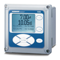
Describes the transmitter display during calibration and programming modes.

1.9 INFRARED REMOTE CONTROLLER

Explains the functions and operation of the infrared remote controller.

1.10 FOUNDATION FIELDBUS

Illustrates the functional block diagram for Fieldbus communication.

1.11 GENERAL SPECIFICATIONS

Provides detailed technical specifications for the 5081-A-FF transmitter.

1.12 ASSET MANAGEMENT SOLUTIONS (AMS)

Describes access and use of AMS for transmitter configuration and monitoring.

1.13 ORDERING INFORMATION

Guides on how to order the Model 5081-A transmitter and its options.

1.14 ACCESSORIES

Lists available accessories for the 5081-A transmitter.

SECTION 2.0 INSTALLATION

2.1 UNPACKING AND INSPECTION

Instructions for checking the transmitter upon arrival and inspecting for damage.

2.2 ORIENTING THE DISPLAY BOARD

Details how to rotate the transmitter's display board for optimal viewing.

2.3 INSTALLATION

General guidelines and procedures for mounting the transmitter.

2.4 POWER SUPPLY WIRING

Explains how to connect the power supply wiring to the transmitter.

SECTION 3.0 SENSOR WIRING

3.1 WIRING MODEL 499A OXYGEN, CHLORINE, AND OZONE SENSORS

Wiring instructions for 499A series amperometric sensors.

3.2 WIRING MODEL 499ACL-01 (FREE CHLORINE) SENSORS AND pH SENSORS

Wiring for free chlorine and pH sensors, including RTD usage.

3.3 WIRING Hx438 AND Gx448 SENSORS

Wiring diagram for Hx438 and Gx448 steam-sterilizable sensors.

SECTION 4.0 INTRINSICALLY SAFE & EXPLOSION PROOF INSTALLATIONS

SECTION 5.0 DISPLAY AND OPERATION WITH INFRARED REMOTE CONTROLLER

5.1 DISPLAY SCREENS

Describes the process and program display screens of the transmitter.

5.2 INFRARED REMOTE CONTROLLER (IRC) - KEY FUNCTIONS

Details the functions of each key on the infrared remote controller.

5.3 MENU TREE

Outlines the navigation structure of the transmitter's menus.

5.4 DIAGNOSTIC MESSAGES

Explains how warning and fault messages are displayed and interpreted.

5.5 SECURITY

Describes the purpose and use of the security code to protect settings.

5.6 USING HOLD

Explains how to use the hold function during calibration to maintain output.

SECTION 6.0 OPERATION WITH FOUNDATION FIELDBUS AND THE DELTAV CONTROL SYSTEM

6.1 OVERVIEW

Introduces the section on Fieldbus operation and software functionality.

6.2 AI BLOCK CONFIGURATION

Explains how to configure Analog Input blocks for measurements and units.

6.3 TRANSDUCER BLOCK OPERATIONS — CONFIGURATION AND CALIBRATION

Details how to configure and calibrate the transducer block using DeltaV Explorer.

6.4 Model 5081-A-FF — DEVICE SUMMARY

Provides a summary of the transmitter's device type, revision, and function blocks.

SECTION 7.0 PROGRAMMING

7.1 GENERAL

Overview of programming tasks and terms used in the section.

7.2 DEFAULT SETTINGS

Lists the factory default settings for the transmitter configuration.

7.3 TEMPERATURE SETTINGS

Explains how to enable/disable and set temperature compensation values.

7.4 DISPLAY

Covers configuring measurement type, units, and output settings.

7.5 CALIBRATION SETUP

Details how to set stabilization criteria and limits for calibration.

7.6 LINE FREQUENCY

Instructions for setting line frequency for noise rejection.

7.7 pH MEASUREMENT

Covers pH correction, diagnostics, and calibration settings.

7.8 BAROMETRIC PRESSURE

Instructions for setting barometric pressure units and values.

SECTION 8.0 CALIBRATION — TEMPERATURE

8.1 INTRODUCTION

Explains the role of temperature in sensor measurements and calibration.

8.2 PROCEDURE USING THE INFRARED REMOTE CONTROLLER

Steps for calibrating temperature using the remote controller.

8.3 PROCEDURE USING DeltaV

Steps for standardizing temperature measurement via DeltaV.

SECTION 9.0 CALIBRATION — OXYGEN

9.1 INTRODUCTION

Explains sensor operation and the purpose of calibration for oxygen.

9.2 PROCEDURE — ZEROING THE SENSOR USING THE REMOTE CONTROLLER

Steps for zeroing the oxygen sensor with the remote controller.

9.3 PROCEDURE — ZEROING THE SENSOR USING DeltaV

Steps for zeroing the oxygen sensor using DeltaV.

9.4 PROCEDURE — AIR CALIBRATION USING THE INFRARED REMOTE CONTROLLER

Steps for air calibration of the oxygen sensor with the remote controller.

9.5 PROCEDURE — AIR CALIBRATION USING DeltaV

Steps for air calibration of the oxygen sensor using DeltaV.

9.6 PROCEDURE — IN-PROCESS CALIBRATION USING THE REMOTE CONTROLLER

Steps for in-process calibration of oxygen sensor with remote controller.

9.7 PROCEDURE — IN-PROCESS CALIBRATION USING DeltaV

Steps for in-process calibration of oxygen sensor using DeltaV.

SECTION 10.0 CALIBRATION — FREE CHLORINE

10.1 INTRODUCTION

Explains sensor operation and calibration for free chlorine measurement.

10.2 PROCEDURE — ZEROING THE SENSOR USING THE REMOTE CONTROLLER

Steps for zeroing the free chlorine sensor with the remote controller.

10.3 PROCEDURE — ZEROING THE SENSOR USING DeltaV

Steps for zeroing the free chlorine sensor using DeltaV.

10.4 PROCEDURE — FULL SCALE CALIBRATION USING THE REMOTE CONTROLLER

Steps for full scale calibration of free chlorine sensor with remote controller.

10.5 PROCEDURE — FULL SCALE CALIBRATION USING DeltaV

Steps for full scale calibration of free chlorine sensor using DeltaV.

10.6 DUAL SLOPE CALIBRATION

Explains dual slope calibration for free chlorine sensors.

SECTION 11.0 CALIBRATION — TOTAL CHLORINE

11.1 INTRODUCTION

Explains sensor operation and calibration for total chlorine measurement.

11.2 PROCEDURE — ZEROING THE SENSOR USING THE REMOTE CONTROLLER

Steps for zeroing the total chlorine sensor with the remote controller.

11.3 PROCEDURE — ZEROING THE SENSOR USING DeltaV

Steps for zeroing the total chlorine sensor using DeltaV.

11.4 PROCEDURE — FULL SCALE CALIBRATION USING THE REMOTE CONTROLLER

Steps for full scale calibration of total chlorine sensor with remote controller.

11.5 PROCEDURE — FULL SCALE CALIBRATION USING DeltaV

Steps for full scale calibration of total chlorine sensor using DeltaV.

11.6 DUAL SLOPE CALIBRATION

Explains dual slope calibration for total chlorine sensors.

SECTION 12.0 CALIBRATION — OZONE

12.1 INTRODUCTION

Explains sensor operation and calibration for ozone measurement.

12.2 PROCEDURE — ZEROING THE SENSOR USING THE REMOTE CONTROLLER

Steps for zeroing the ozone sensor with the remote controller.

12.3 PROCEDURE — ZEROING THE SENSOR USING DeltaV

Steps for zeroing the ozone sensor using DeltaV.

12.4 PROCEDURE — FULL SCALE CALIBRATION USING THE REMOTE CONTROLLER

Steps for full scale calibration of ozone sensor with remote controller.

12.5 PROCEDURE — FULL SCALE CALIBRATION USING DeltaV

Steps for full scale calibration of ozone sensor using DeltaV.

SECTION 13.0 CALIBRATION — pH

13.1 INTRODUCTION

Explains pH measurement principles and calibration importance.

13.2 PROCEDURE — AUTO CALIBRATION USING THE REMOTE CONTROLLER

Steps for automatic pH calibration using the remote controller.

13.3 PROCEDURE — AUTO CALIBRATION USING DeltaV

Steps for automatic pH calibration using DeltaV.

13.4 PROCEDURE — MANUAL CALIBRATION USING THE REMOTE CONTROLLER

Steps for manual pH calibration using the remote controller.

13.5 PROCEDURE — MANUAL CALIBRATION USING DeltaV

Steps for manual pH calibration using DeltaV.

13.6 STANDARDIZATION USING THE INFRARED REMOTE CONTROLLER

Procedure for standardizing pH measurement with the remote controller.

13.7 STANDARDIZATION USING DeltaV

Procedure for standardizing pH measurement using DeltaV.

13.8 pH SLOPE ADJUSTMENT USING THE INFRARED REMOTE CONTROLLER

How to adjust pH slope using the remote controller.

13.9 pH SLOPE ADJUSTMENT USING DeltaV

How to adjust pH slope using DeltaV.

SECTION 14.0 DIAGNOSTICS

14.1 GENERAL

Introduction to transmitter diagnostics and how to access them.

14.2 DIAGNOSTIC MESSAGES FOR DISSOLVED OXYGEN

Lists diagnostic messages specific to dissolved oxygen measurements.

14.3 DIAGNOSTIC MESSAGES FOR OZONE AND TOTAL CHLORINE

Lists diagnostic messages for ozone and total chlorine measurements.

14.4 DIAGNOSTIC MESSAGES FOR FREE CHLORINE

Lists diagnostic messages for free chlorine measurements.

SECTION 15.0 TROUBLESHOOTING

15.1 WARNING, FAULT, AND ERROR MESSAGES

Explains the meaning and display of warning, fault, and error messages.

15.2 TROUBLESHOOTING WHEN A FAULT, WARNING, OR ERROR MESSAGE IS SHOWING

Table of faults, warnings, and errors with their explanations and corresponding sections.

15.3 TEMPERATURE MEASUREMENT AND CALIBRATION PROBLEMS

Troubleshooting common issues related to temperature measurement and calibration.

15.4 OXYGEN MEASUREMENT AND CALIBRATION PROBLEMS

Troubleshooting issues specific to oxygen measurement and calibration.

15.5 FREE CHLORINE MEASUREMENT AND CALIBRATION PROBLEMS

Troubleshooting problems with free chlorine measurement and calibration.

15.6 TOTAL CHLORINE MEASUREMENT AND CALIBRATION PROBLEMS

Troubleshooting issues related to total chlorine measurement and calibration.

15.7 OZONE MEASUREMENT AND CALIBRATION PROBLEMS

Troubleshooting problems with ozone measurement and calibration.

15.8 pH MEASUREMENT AND CALIBRATION PROBLEMS

Troubleshooting issues related to pH measurement and calibration.

15.9 SIMULATING INPUT CURRENTS - DISSOLVED OXYGEN

Simulating input currents for dissolved oxygen sensor performance checks.

15.10 SIMULATING INPUT CURRENTS - CHLORINE AND OZONE

Simulating input currents for chlorine and ozone sensor performance checks.

15.11 SIMULATING INPUTS - pH

Simulating pH inputs for transmitter testing.

15.12 SIMULATING TEMPERATURE

Simulating temperature inputs for transmitter testing.

15.13 MEASURING REFERENCE VOLTAGE

Procedure for checking the reference electrode voltage.

SECTION 16.0 MAINTENANCE

16.1 OVERVIEW

Introduction to the maintenance section.

16.2 TRANSMITTER MAINTENANCE

Routine cleaning and component replacement guidelines.

SECTION 17.0 RETURN OF MATERIAL

17.1 GENERAL

General information regarding factory communication for repairs.

17.2 WARRANTY REPAIR

Procedure for returning instruments under warranty for repair.

17.3 NON-WARRANTY REPAIR

Procedure for returning instruments no longer under warranty for repair.

APPENDIX A BAROMETRIC PRESSURE AS A FUNCTION OF ALTITUDE

Related product manuals