!# '(#"
!"(""
'(#"
!"(""
#*&*+
0?@JJ<:K@FE>@M<J><E<I8CGIF:<;LI<J=FIIFLK@E<D8@EK<E8E:<F=K?<KI8EJD@KK<I0?<KI8EJD@KK<IE<<;J
8CDFJKEFIFLK@E<D8@EK<E8E:<
(&"'!((&!"(""
,<I@F;@:8CCP:C<8EK?<KI8EJD@KK<IN@E;FNN@K??FLJ<?FC;8DDFE@8FI>C8JJ:C<8E<I0?<;<K<:KFI=FIK?<@E=I8I<;
I<DFK<:FEKIFCC<I@JCF:8K<;9<?@E;K?<N@E;FN8KK?<KFGF=K?<KI8EJD@KK<I=8:<0?<N@E;FN@E=IFEKF=K?<;<K<:
KFIDLJK9<B<GK:C<8E
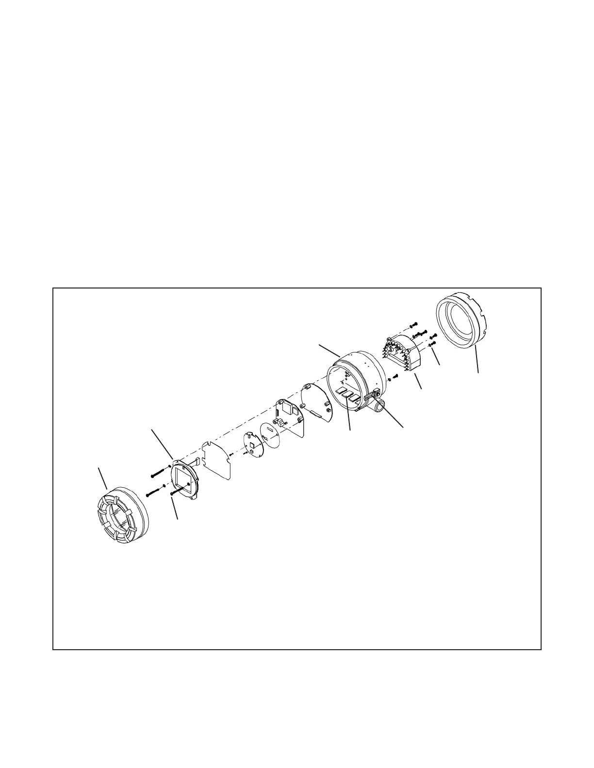
)FJK:FDGFE<EKJF=K?<KI8EJD@KK<I8I<I<GC8:<89C<.<=<IKF"@>LI<8E;089C<=FIG8IKJ8E;G8IKELD9<IJ
)& G?;>343*84F>5!>34;(A0=B<8CC4A
Three screws (part 13 in the drawing) hold the circuit boards in place. Removing the screws allows the display board
(part 2) and the CPU board (part 3) to be easily removed. A ribbon cable connects the boards. The cable plugs into
the CPU board and is permanently attached to the display board. A 16 pin and socket connector holds the CPU and
analog (part 4) boards together. Five screws hold the terminal block (part 5) to the center housing (part 7), and the
16 pins on the terminal block mate with 16 sockets on the back side of the analog board. Use caution when sepa-
rating the terminal block from the analog board. The pin and socket connection is tight.
}

 Loading...