2
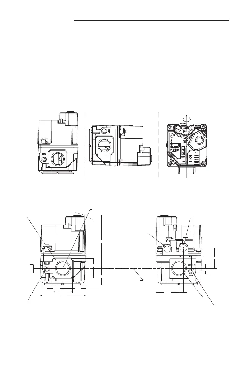
360˚
MOUNTING POSITIONS:
Upright, or 0° to 90° from upright
UPRIGHT
LEFT or RIGHT
INLET BOSS
VERTICAL
Figure 1. Gas Valve Mounting Positions
REGULATOR COVER SCREWS
(REG. ADJ. BENEATH THESE
SCREWS)
TERMINAL – M (MAIN)
TERMINAL –
P (PILOT/REDUNDANT)
TERMINAL – C (COMMON)
TERMINAL – HI (2ND STAGE COIL)
PILOT GAS OUTLET
PLUG OR FITTING
CENTERLINE OF
INLET & OUTLET
Note: All dimensions indicated in inches
INLET PRESSURE TAP
1/8” - 27 NPT
OUTLET PRESSURE TAP
1/8” - 27 NPT
OUTLET 3/4” - 14 NPT
1.63 .32
.19
1.45
.88
3.77
1.375
1.20
1.63
3.26
1.375
1.13
.03
VENT PLUG
1/8”-27 NPT
INLET 3/4” - 14 NPT
or 1/2” - 14 NPT
4.20 R
SWING RADIUS
3.98 INLET TO
OUTLET
3/16
”
GROUND
TERMINAL
ON/OFF SWITCH
PILOT ADJUSTMENT
COVER SCREW
(PILOT ADJ. BENEATH
THIS SCREW)
Parts and Accessories:
Natural to Regulated LP Gas Conversion Kits, regulation range 5” to 12” W.C.:
• 92-0659 included with single stage models or F92-0659 available separately
• 92-1008 included with two-stage models or F92-1008 available separately
• Two 92-0659 kits may be used for two-stage valve
• Pilot tting 0092-080800 included or F69-0727 available separately
Figure 2. Valve Dimensions and Features
SPECIFICATIONS
PRECAUTIONS
 Loading...


