Encoder Connections
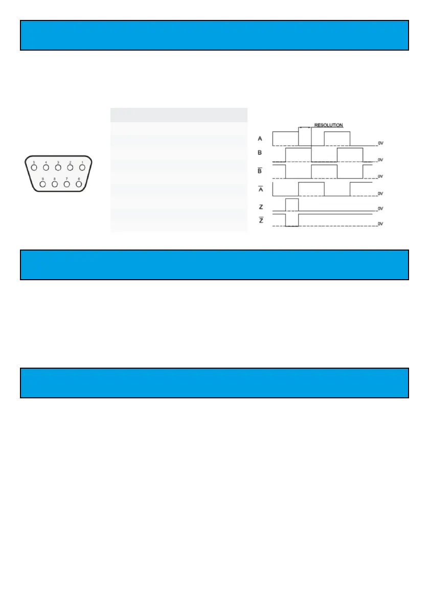
All ems-i DRO and linear encoders (apart from special products) have the same encoder
connection specification and pin-out. As such any ems-i encoder can work on any ems-i
DRO. In addition, all of these DRO and encoders are full industrial EIA 422 differential and
screened to ensure the highest levels of noise immunity and performance.
Power-up Sequence
On power-up the EM250 DRO will make a few ‘BEEPS’ and all the axis windows will cycle
through the LED numbers 1, 2, 3, 4, 5, 6, 7, 8, 9, 0 and the message windows will show EMS-I.
This is to test the beep and the LED displays. It also puts the DRO under maximum current
load. As such if there is an issue with the DRO supply the DRO will most likely have an issue
during this process. If this occurs please consult the Troubleshooting section for assistance.
EM250 Models
The EM250 DRO is available in 4-versions, each machine type specific.
● 2-axes Lathe
● 3-axes Lathe
● 2-axes Milling
● 3-axes Milling
ems-i have a full range of DRO available for all machine applications from simple saws and
1-axis options through to 5-axes and full TFT LCD displays. As such whatever your
requirement you will be able to find a solution with ems-i.
Pin Signal
1 Z (ABS reference)
2 /Z (/ABS reference)
3 VCC (+5VDC)
4 Shield
5 GND (0V)
6 Phase A
7 Phase /A
8 Phase /B
9 Phase B
9 Pin ‘D’ type Plug
connector
- 40 -
 Loading...