Ascent Oil – August 2019 24
TROUBLESHOOTING THE SAFETY PRESSURE SWITCHES (ASCENT PLUS ONLY)
In addition to the blocked vent (puff) switch present on all Ascent boilers, the Ascent Plus has two additional pressure
switches and a stack temperature limit switch to ensure safe operation in the event of several possible failure conditions.
The blocked vent switch measures the over fire pressure to ensure the boiler maintains negative pressure in the boiler
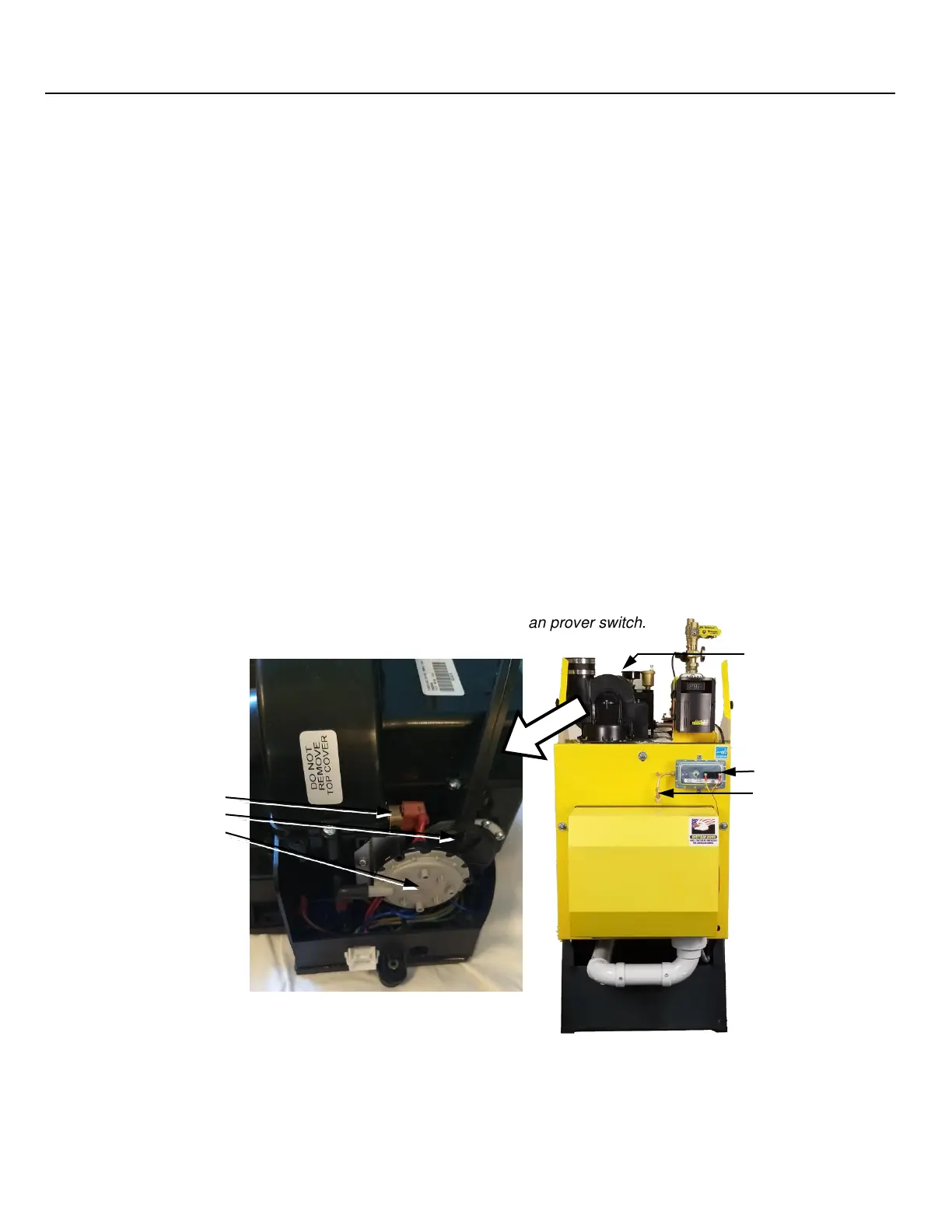
before the Dilution Air Exhaust Fan (inducer). The fan prover switch ensures the dilution-air blower is operating and allows
the burner to fire. The blocked intake switch ensures the fresh air intake has not become obstructed. The blocked vent
(puff) switch is connected to the ‘BV’ terminals on the burner primary control on the Ascent and Ascent Plus models, while
the fan prover and blocked intake switches are connected in series with the burner motor power on the Ascent Plus model
only.
If the ‘BV’ terminal is an open-circuit, the blocked vent switch has opened the burner will recycle and eventually lockout.
Measure the pressure at the over-fire test port and ensure the boiler is operating at negative pressure. If the switch
remains open despite continuous negative pressure overfire, replace the switch.
If the burner motor fails to run (resulting in a lockout), it is likely that the blocked intake normally-closed switch has
opened, or the normally-open Dilution Air Exhaust Fan prover switch has failed to close. By process of elimination, which
switch is causing the failed motor condition may be quickly determined.
The blocked intake switch can be disabled by removing the flex tubing on the Dilution Air Exhaust Fan (inducer)
assembly that connects it to the pressure tap. After removing the tube, run the burner and check for a failed motor
condition. Attach a monometer to the plastic nipple that the flex tubing was attached to. The intake must not be more
negative than -1.00” w.c. of vacuum (-0.50 to -0.85” w.c. is typical). If the intake is showing high vacuum (and the burner
now runs with the switch disabled), check for signs of a blockage in the intake and ensure that the intake length is shorter
than 50’ (with each elbow counting as 5’ equivalent length).
The final switch to check is the normally-closed Dilution Air Exhaust Fan proving switch. Check continuity from the
motor terminal on the burner primary control to the orange motor power lead in the burner primary control junction box.
With the boiler off, the circuit should be open. Once the dilution-air blower turns on, the circuit should close. If the dilution
air blower fails to turn on, ensure there is power reaching the Molex connector on the blower assembly. If the blower turns
on, check for power at the burner motor lead. If you have no power at the burner motor, replace the dilution air blower
assembly or fan prover switch.
NOTE the dilution air switch will not prove if there is no venting attached; an elbow or a short length of pipe is required to
provide adequate backpressure to close the Dilution Air Exhaust Fan prover switch.
Dilution Air Exhaust Fan
(inducer) housing shown
with enclosure cover
removed
Blocked Intake switch,
and stack limit switch
 Loading...