QUICK INSTALL GUIDE
A ) Download the Enphase Installer App version 3.X mobile app and open it to
log on to your Enphase Installer App account. With this app, you can con-
nect to the IQ Gateway to track system installation progress. To download,
go to https://enphase.com/installers/apps.
B) Check the box for the following items:
•
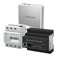
IQ Combiner 5 or 5C with IQ Gateway printed circuit board. The X-IQ-AM1-
240-5C also includes an LTE-M1 cell modem.
•
A pair of clamp CTs for consumption metering
•
One clamp CT for IQ Battery 5P monitoring
•
IQ Combiner 5/5C Quick Install Guide (this document)
C ) Make sure you have the following required items:
• For all Enphase Energy System Installations, a control signal cable is required
and must be purchased separately (for installations with IQ Battery 5P or IQ
System Controller 3), Enphase SKU for control cable: CTRL-SC3-NA-01.
•
Tools: Screwdriver, pliers, and torque wrench.
•
Up to four Eaton BR-style breakers (one for each PV branch circuit). Eaton
BR-style breakers are the only breakers you can use. You can install upto
60 A breaker(s) in the IQ Combiner (order Enphase BRK-10A-2-240V, BRK-15A-
2-240V, BRK-20A-2P-240V, Eaton BR210, Eaton BR215, Eaton BR220, Eaton
BR230, Eaton BR240, Eaton BR250, and/or Eaton BR260 circuit breakers). The
sum of all distributed energy resources (DER) branch breaker ratings cannot
exceed 80 A. For IQ8 systems with IQ System Controller, use BRK-15A-2P-
240-B(or Eaton BR215B) for 15 A circuits and BRK-20A-2P-240-B(or Eaton
BR220B) for 20 A circuits to be compatible with the hold-down kit. The IQ
Gateway breaker should not exceed 15 A and is counted separately (total
90 A/95 A worth of breakers).
•
Up to two hold-down kits with screws for the breakers. Each hold-down kit
(X-IQ-NA-HD-125A) will allow the installation of up to two breakers located on the
same side of the busbar (only for IQ8 PV installations with IQ System Controller).
•
Overcurrent protection in the load center in accordance with NFPA
70, 705.12. and NEC 690
•
Suitable mounting hardware: Use #8 (or larger) screws that are long enough
to secure the unit to the vertical mounting surface
•
Copper conductors rated for wet locations and sized to meet local code
requirements and voltage drop/rise considerations. Wire sizes and torque
values are listed on the door of the unit.
•
UL-listed rain-tight conduit hubs for wire entry into the enclosure.
D ) For consumption metering, check that there is enough space in the load
center to install CTs. Do not install the CTs in a panel where they exceed
75% of the wiring space of any cross-sectional area within the load center.
E ) Decide how to connect the IQ Gateway to the internet: Use Wi-Fi and
Enphase Mobile Connect, or Ethernet. Then, make sure you have
(Models: X-IQ-AM1-240-5C and X-IQ-AM1-240-5)
Installing the IQ Combiner 5 and IQ Combiner 5C
F ) Make note of the IQ Gateway serial number on the installation map. Later,
you will need to enter this number in Enphase Installer App. You can type it in
manually or scan the label on the inside of the combiner door. Always keep a
copy of the installation map for your records.
G ) Note that installation of the IQ Combiner 5/5C has two parts: To ensure suc-
cessful device detection, complete Part 2 after installing any IQ Microinverter,
IQ Battery 5P, and/or IQ System Controller.
The information contained in this document is the
proprietary and confidential information of ENPHASE
ENERGY, Inc.. You will not provide, make available
or disclose (or use for any purpose other than that
contemplated by this document) any such information
to any other party without the express, written consent
of ENPHASE ENERGY, Inc.
01
02
REVISIONS
REV DESCRIPTION CHKD DATE
ECO-006239 - INITIAL RELEASE
NOTES:
1. MATERIAL: 3M 7871 POLYESTER BASE MATERIAL,
3M ADHESIVE - 350 HIGH BONDING ACRYLIC ADHESIVE WITH CLEAR OVERLAY ON FRONT.
2. BACKGROUND COLOUR: WHITE, CONTENT COLOUR : CMYK. FOLLOW .ai FILE FOR LABEL PRINTING.
3. USE UV RESISTANT INK
4. COMPLETED LABELS TO BE PACKAGED WITH PART NUMBER AND REVISION, MFG CODE AND DATE.
5. SUBMIT ALLARTWORK PROOFS FOR APPROVAL PRIOR TO PRINTING.
6. LABEL MUST BE UL RECOGNIZED (PGDQ2) AND CSA ACCEPTED AS SUITABLE FOR OUTDOOR USE AT
TEMPERATURES FROM -40°C TO +65°C AND SUITABLE FOR THE SURFACE TO BE APPLIED (PER UL RECOGNIZED
COMPONENT DIRECTORY). EACH LABEL MUST BE MARKED WITH VENDOR’S MARK AS DEFINED IN THE CSA LIST OF
ACCEPTED ADHESIVE-TYPE NAMEPLATES. THE SMALLEST SHIPPING PACKAGE MUST BE MARKED WITH SUPPLIER’S
NAME AND UL DESIGNATION.
7. FINISHED PART MUST BE ROHS COMPLIANT (EU ROHS DIRECTIVE 2015/863/EU). MANUFACTURER WILL BE
REQUIRED TO CERTIFY ROHS COMPLIANCE. IF THERE IS A CONFLICT BETWEEN THE SPECIFICATIONS AND
ROHS COMPLIANCE, THE VENDOR MUST CONTACT ENPHASE FOR CLARIFICATION.
8. ALL DIMENSIONS ARE IN MILLIMETERS.
780-01013
1 1
Wiring Diagram Label,
AC IQ Combiner Box 5
06
SIZE
SHEET OF
REVDRAWING NO.
DWN BY
ENGR
MFG
TITLE
THIRD ANGLE PROJECTION
3D MODEL
APPROVALS
DATE
C (A2)
DO NOT SCALE THIS DRAWING
ADITYA NATU
30-MAR-23
30-MAR-23
ADITYA NATU
HW
RP
06-MAY-22
02-NOV-22
03
AKC 13-DEC-22
AKC
10-JAN-23
ECO-006641 - LABEL UPDATE04
NA
NA
IQ Gateway
1 2 3 4
NO
Ref
Common
C
Digital Input Relay
PD, B300
OVC II
L1 L2
L3
N
CU, 75C, 14AWG MIN
MEAS CAT III
OVC III
RECOMMENDED ROUTING
FOR ETHERNET CABLE
230+/-0.3
CUT LINE MEASUREMENT
LOAD CENTER
AC
NEUTRA L
MA IN
LUG
PV CT
GRID-TIED SYSTEMS
IQ Gateway
1 2 3 4
NO
Ref
Common
C
Digital Input Relay
PD, B300
OVC II
L1 L2
N
CU, 75C, 14AWG MIN
MEAS CAT III
OVC III
LOAD CENTER
L1 L2
TO MAIN LOAD CENTER/
IQ SYSTEM CONTROLLER/
IQ BATTERY 5P
TO MAI N LOAD CENTER
AC
NEUTRA L
MA IN
LUG
TO PV
TO PV
PV CT
GRID-FORMING SYSTEMS
380+/-0.3
To IQ System
Controller 3/3G
WARNING:
- IQ8 Grid-Tied Systems: IQ Gateway must be
powered from IQ Combiner’s Breaker
- IQ8 Grid-forming Systems: IQ Gateway must
be powered from IQ System controller
1
2
3
4
1
2
3
4
5
5
L3
1
1
2
2
3
3
4
4
NA
NA
1
1
2
2
3
3
4
1
2 3
4
1 2 3
4
4
CTRL L (BLUE)
CTRL H (ORANGE)
CTRL G (BLACK)
NA
DRAIN
CTRL L (BLUE)
CTRL H (ORANGE)
CTRL G (BLACK)
NA
DRAIN
1
1
2
2
3
3
4
1 2 3
4
1 2 3
4
4
Terminating node : CTRL(CONTROL) Wiring
CTRL L (BLUE)
CTRL H (ORANGE)
CTRL G (BLACK)
NA
DRAIN
NA
NA
NA
NA
NA
NA
NA
NA
IQ Combiner LED & buttons quick reference guide
AP mode button
Only used by installer during installation or to configure the system.
Starts IQ Gateway’s wireless Access Point (AP) to connect mobile phone directly.
Device scan button
Only used by installer during installation or to configure the system.
Starts/stops a 15-minute scan for devices over the power line.
Enphase Installer Platform (EIP) communication LED
Red when connected to local network only i.e., no internet.
Green when connected to Enphase’s EIP cloud.
Flashing green when connecting to EIP or WiFi router.
Off if no network is available
Usually red at dawn/dusk, off at night & flashing red after IQ Gateway restarts.
Power production LED
Flashing red when microinverters are not yet detected.
Red if one or more microinverters stop producing power.
Green light when all microinverters are producing power.
Flashing green when an upgrade of the microinverters is in progress.
Off if all the microinverters stop producing or communicating.
Off is default unless installer is using AP mode.
AP mode LED
Green when AP mode is enabled, and IQ Gateway Wi-Fi network is available.
Off when AP mode is disabled.
Device communication LED
Usually red during dawn/dusk and off at night.
Green when all provisioned microinverters are communicating with IQ Gateway.
Off if all microinverters are not communicating with IQ Gateway.
Flashing green when IQ Gateway is scanning for microinverters.
Red if one or more microinverters are not communicating with IQ Gateway.
All LED’s
Flashing green when software upgrade is in progress.
Flashing red when IQ Gateway is booting up.
On Power-Up, LEDs can take up to 30 seconds to glow.
While restarting, wait for 2 minutes after powering off the IQ Gateway, before powering it back on.
CTRL H CTRL High Signal
CTRL L CTRL Low Signal
GROUND Ground Signal
NA Unused
DRAIN CTRL Shield
Designed in California and India. Made in Mexico
Dedicated solar and DG Combiner Box - do not add loads
10 AMP or 15 AMP IQ Gateway Breaker not used for backfeed
Photovoltaic
Combiner Box
X-IQ-AM1-240-5
IQ Combiner 5
Electrical ratings
For DG breaker, use only Eaton BR series.
Voltage
DG Breakers
DG Inputs
Output
Temperature
S/N:
P/N:
240VAC, 60Hz
80A MAX (combined)
64A MAX (combined)
65A MAX, 90A MAX feeder OCPD
46°C MAX ambient
Connection
Wire sizes
Torque
DG Breaker
(1, 2, 3, 4)
14-10 AWG
8 AWG
6-4 AWG
4-1/0 AWG
14-10 AWG
5.0 Nm (45 lb-in)
2.26 Nm (20 lb-in)
60A Circuit Breaker only
IQ Gateway Breaker (5)
IQ Gateway Power Terminals
Neutral
and ground
Large screw
CTRL Cables (C1,C2)
Drain Cables (C3)
Small screw
Main lug
CTRL
Connectors
Copper conductors only, rated min. 75°C.
Follow NFPA 70 (NEC), or CSA C22.1 part 1, and all local codes.
For DG Breakers larger than 20A, use wire insulated for 90°C
based on 75°C ampacities.
2-1/0 AWG
14-3 AWG
6 AWG
8 AWG
10-14 AWG
10-4 AWG
3-2/0 AWG
18 AWG
18 AWG
5.0 Nm (45 lb-in)
5.6 Nm (50 lb-in)
0.2 Nm (1.77 lb-in)
0.2 Nm (1.77 lb-in)
5.6 Nm (50 lb-in)
5.1 Nm (45 lb-in)
3.6 Nm (32 lb-in)
2.3 Nm (20 lb-in)
2.6 Nm (23 lb-in)
2.2 Nm (20 lb-in)
2.8 Nm (25 lb-in)
3.0 Nm (27 lb-in)
P1 C1 C2
C3
Production | Consumption
P1 C1 C2
C3
Production | Consumption
CT on consumption L2
CT on consumption L1
CT on IQ Battery L2
CT on PV L1
ECO-006543 - WIRING COLOUR CHANGE
RECOMMENDED ROUTING
FOR ETHERNET CABLE
Jumper
Jumper
CT on consumption L2
CT on consumption L1
CT on PV L1
When IQ System Controller 3/3G and/or IQ Battery 5P are on both sides of IQ Combiner and
both CTRL terminals are used.
When IQ System Controller 3/3G and IQ Battery 5P units are on only one side of IQ Combiner
and only one CTRL terminal is used.
120 ohms, 0.25W
WARNING: WIRE THE DRAIN ONLY ON ONE END OF THE CONTROL CABLE
WARNING: WIRE THE DRAIN ONLY ON ONE END OF THE CONTROL CABLE
C1
C2
C3
C1
C2
C3
1.4 Nm (12.4 lb-in)
14-10 AWG
CTRL Board
CTRL Board
CTRL Board
CTRL Board
C1
C1
C2
C2
C3
C3
ECO-006639 - LABEL UPDATE
1 2
1 2
1 2
1
2
Non terminating node : CTRL(CONTROL) Wiring
05
AKC
30-MAR-23
ECO-007021 - LABEL & NOTE 2 UPDATE &
PANTONE COLOUR CODE TABLE ADDED
1
2
3 4
1
2
3 4
05
IQ GATEWAY CONTAINS
FCC ID: WS2-WG78DBV0
IC ID: 10462A-WG78DBV0
CTRL BOARD CONTAINS
FCC ID: MCQ-XBEE3
IC ID: 1846A-XBEE3
05
ONLY FOR REFERENCE
Colour Pantone Colour Code
COOL GREY 1C
COOL GREY 3C
PANTONE 266 C
PANTONE 725 C
PANTONE 2252 C
PANTONE BLUE 072 C
PANTONE 2347 C
PANTONE 1585 C
PANTONE BLACK 6C
CT on IQ Battery L2
06 ECO-007140 - LABEL UPDATE AKC 02-MAY-23
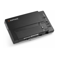
IMPORTANT: The IQ Gateway inside the IQ Combin-
er is required to monitor the performance of the IQ
Microinverters and to communicate with IQ Battery
5P and IQ System Controller.
IQ Battery or
Generator
power line
over
line
meter
Wi-Fi
and
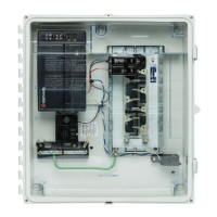
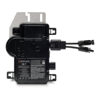
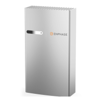
The IQ Combiner 5/5C combine up to four AC branch circuits
of IQ Series Microinverters and/or IQ Batteries. To install the IQ
Combiner 5/5C, read and follow all warnings and instructions
in this guide. Safety warnings are listed at the end of this guide.
If you do not fully understand any of the concepts, terminology,
or hazards outlined in these instructions, refer installation to a
qualied electrician or installer. These instructions are not meant
to be a complete explanation of a renewable energy system.
All installations must comply with national and local electrical
codes. Professional installation is recommended.
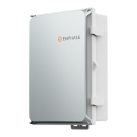
The IQ Combiner 5/5C have an outdoor-rated, NRTL-certied
NEMA type 3R enclosure containing an IQ Gateway, circuit
breakers, a pair of consumption metering CTs, an IQ Battery
5P metering CT, and wiring for IQ Gateway connections. The IQ
Combiner 5C includes a Mobile Connect LTE-M1 cell modem.
Use the IQ Combiner 5C for single-phase applications and to
support the AC connections needed for an Enphase residential
solar installation.
NOTE: The IQ Combiner 5/5C is compatible with IQ Battery
5P and IQ System Controller 3/3G. It is not compatible with IQ
Battery 3/10/3T/10T and IQ System Controller 1/2.
•
Enphase Mobile Connect (included with X-IQ-AM1-240-5C)
•
Ethernet cable: 802.3, Cat5E or Cat6, unshielded twisted pair (UTP). Do not use
shielded twisted pair (STP) cable.
When installing with an Enphase Energy System, both Enphase Mobile Connect and
additional internet connection (Wi-Fi or Ethernet) are required.
PREPARATION
NOTE: IQ Combiner 5/5C can be used for grid interactive (i.e., grid-tied) as well as
multi-mode (i.e., grid-forming) installations.
Warning! Risk of equipment damage. Instructions for wiring
grid-forming systems are different from grid-tied systems.
Follow specic wiring instructions as outlined herein to main-
tain warranty.
the following optional items, if needed:
PRELIMINARY


 Loading...