1
QUICK INSTALL GUIDE
PREPARATION
A ) Download the Enphase Installer App version 3.X mobile app and open it to
log on to your Enphase Installer App account. With this app, you can con-
nect to the IQ Gateway to track system installation progress. To download,
go to enphase.com/toolkit.
B) Check the box for the following items:
•
Enphase IQ Combiner 4 or 4C with IQ Gateway printed circuit board.
The X2-IQ-AM1-240-4C also includes an LTE-M1 cell modem.
•
A pair of split-type or clamp-type consumption metering CTs.
•
Enphase IQ Combiner 4/4C Quick Install Guide (this document).
C ) Ensure you have the following items:
•
An Enphase Energy System Communications Kit (COMMS-KIT-01 ) is not
included. It is required for all Enphase Energy System installations and must
be purchased separately (only for installations with IQ battery or IQ System
Controller).
•
Tools: screwdriver, pliers, and torque wrench.
•
Up to four Eaton BR-style breakers (one for each PV branch circuit).
Eaton BR-style breakers are the only breakers you can use. You can
install 10A, 15A, 20A, 30A, 40A, 50A, or 60A breaker(s) in the IQ Combiner
(order Enphase BRK-10A-2-240V, BRK-15A-2-240V, BRK-20A-2P-240V,
Eaton BR210, Eaton BR215, Eaton BR220, Eaton BR230, Eaton BR240,
Eaton BR250, and Eaton BR260 circuit breakers).
The sum of all Distributed Energy Resources (DER) branch breaker
ratings cannot exceed 80 A. For IQ8 systems with IQ System Controller,
use BRK-15A-2P-240-B for 15 A circuits and BRK-20A-2P-240-B for 20 A
circuits to be compatible with the hold down kit. You can also use Eaton
BR215B and Eaton BR220B breakers for IQ8 systems. The IQ Gateway
breaker should not exceed 10 A and is counted separately (total 90 A
worth of breakers).
•
Up to two hold-down kits with screws for the breakers. Each hold-down
kit (X-IQ-NA-HD-125A) allows installation of up to two breakers located on
the same side of the busbar (only for IQ8 PV installations with IQ System
Controller).
(Model X2-IQ-AM1-240-4 and X2-IQ-AM1-240-4C)
How It Works
Installing the Enphase IQ Combiner 4 and
Enphase IQ Combiner 4C
The Enphase IQ Combiner 4
and IQ Combiner 4C combine up to
four AC branch circuits of Enphase IQ
Series Microinverters and Enphase
IQ Batteries.
To install the IQ Combiner 4 or 4C, read
and follow all warnings and instructions in this guide.
Safety warnings are listed on the back of this guide.
If you do not fully understand any of the concepts,
terminology, or hazards outlined in these instructions, consult a qualied
electrician or installer. These instructions are not meant to be a complete
explanation of a renewable energy system. All installations must comply with
national and local electrical codes. Professional installation is recommended.
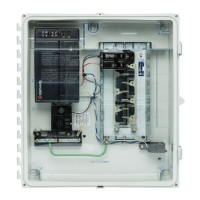
The IQ Combiner 4C and 4 have an outdoor-rated, NRTL-certied
NEMA type 3R enclosure containing an Enphase
IQ Gateway™, circuit
breakers, a pair of split-type or clamp-type consumption metering CTs,
and wiring for IQ Gateway connections. The IQ Combiner 4C includes a
Enphase Mobile Connect™ LTE-M1 cell modem. Use the IQ Combiner 4C
for single-phase applications and to support the AC connections needed
for an Enphase residential solar installation.
NOTE: This product is IEEE1547-2018 compliant.
Generator
(reserved for future use*)
Enphase Cloud
IMPORTANT: The IQ Gateway inside
the IQ Combiner is required to monitor
performance of the IQ microinverters
and to communicate with IQ Battery
and IQ System Controller.
IQ GATEWAY
P1 C1 C2
1 2 3 4
NO
Ref
Common
C
Digital Input Relay
PD, B300
OVC II
L1 L2
N
CU, 75C, 14AWG MIN
MEAS CAT III
OVC III
Production | Consumption
RECOMMENDED ETHERNET
CABLE ROUTING
LOAD CENTER
L1 L2
TO IQ
BATTERY / PV
TO MAIN
LOAD
CENTER
AC
NEUTRAL
MAIN
LUG
(IF PV, MUST PASS TH ROUGH
PRODUC TION CT)
TO PV
CT
Junction
clip
NE Filter
Board
TO
IQ Sytem
Controller
(optional)
Figure A: Combiner 4 units with split-type Consumption CTs
NOTE: On-grid forming IQ8 Systems, the IQ Gateway L1 and L2 must
NOT be wired to the combiner circuit breaker. The IQ Gateway L1 and L2
can be wired to:
• A double pole breaker on the generator breaker spot in IQ System
Controller if the spot is unused
• A double pole breaker on the backed-up loads subpanel
• A quadplex (BQC220240 or BQC215240) breaker on the NFT break-
er position in IQ System Controller



 Loading...