Manage the cabling
A ) Attach the cables to the racking with cable clips or tie wraps. Add at
least one every 1.8 m (6 feet).
B ) Dress any excess cabling in loops so that it does not contact the roof.
Do not form loops smaller than 12 cm (4.75 inches) in diameter.
5
Cable clip
Energise the system
A ) Turn ON the AC disconnect or circuit breaker for the branch circuit.
B ) Turn ON the main utility-grid AC circuit breaker. Your system will start
producing power after a ve-minute wait time.
C ) Check the LED on the connector side of the microinverter:
LED Indicates
Flashing
green
Normal operation. AC grid function is normal, and there
is communication with the IQ Gateway.
Flashing
orange
The AC grid is normal, but there is no communication with
the IQ Gateway. This is normal until you complete Step 7.
Flashing red The AC grid is either not present or not within specication.
Solid red There is an active “DC Resistance Low, Power Off” (GFI
Tripped) condition. Use the Enphase Installer Portal to reset it,
or refer to the Enphase IQ Gateway Installation and Operation
Manual at: https://enphase.com/en-gb/installers/resources/
documentation for more information.
6
Reinstall the AC module
A ) Reinstall the AC Module (panel) on the roof or other mounting
location per manufacturer instructions.
B ) If needed, retrieve the DC adapter that you saved when removing
the failed microinverter, and connect the adapter to the replacement
microinverter.
C ) Attach the IQ Cable connector to the DC connector on the replace-
ment microinverter. Make sure the connection is fully seated.
D ) Listen for clicks as the connectors engage.
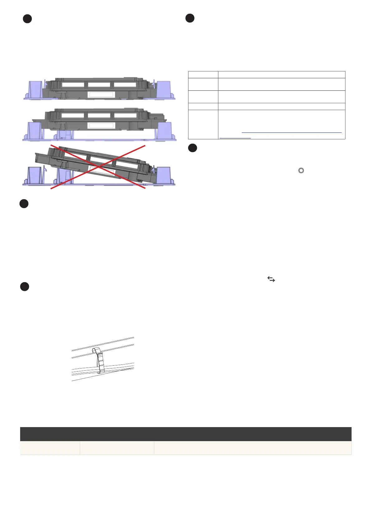
4
Non-functional position
Functional position
Tilted, incorrect
3
Check the Microinverter position
A ) Check the replacement microinverter against the images in the step.
B ) If the microinverter is not in the functional position, use both hands to
lift the microinverter up. You will hear four clicks as the microinverter
locks into the installation position.
C ) Ensure the microinverter is aligned correctly and all four latches are
locked.
Retire the unit and update the array
Option 1: Retire and Replace
A ) In the Enphase Installer Portal, look for the “Retire and Replace” feature
on the “Settings” page by clicking the gear icon .
C ) Scroll to the self-help section and click “Install Replacement”.
D ) Enter the old microinverter serial number and then the replacement
serial number and click “Submit”.
All the administrative steps are taken care of for you.
NOTE: Until the microinverter reports to Enphase Installer App the panel will
remain grey.
Option 2: Retire the unit and update the array
A ) While still at the site, start a device scan at the IQ Gateway to detect the
new unit:
•
For older IQ Gateways, press and hold the IQ Gateway Menu button
on the right edge of the IQ Gateway. After two seconds, the IQ
Gateway menu appears. Continue holding the Menu button. When
the LCD screen displays “Enable Device Scan”, release the Menu
button.
•
For IQ Gateway, press the “Device Scan” button (lower button). The
Device Communications LED ashes green during the scan.
(Alternatively, you can initiate a scan using the Enphase Installer
App.)
NOTE: Complete the following steps when you are back in the ofce.
B ) Retire the replaced microinverter, by logging into Enphase Installer
Portal and locating the array in your Installer Dashboard. Access the
array and click on the unit that has been replaced. Click the device
serial number and then click the “Retire” button at the top of the
screen.
C ) Place the new microinverter in the virtual array by returning to the array
overview screen and clicking the gear icon in the upper right. Scroll down
to the Array Details pane, and open Array Builder. Locate and click on the
unit that has been replaced and click “Unassign” on the top toolbar. Drag
the newly installed unit in to the empty module position in the array and
click “Save”.
7
Revision history
REVISION DATE DESCRIPTION
140-00157-04 June 2023 Updated the document for product names and editorial changes.
 Loading...


