2
Manage the cabling
A ) You must install supports (clips, etc.) for the
QD Cable and Raw QD Cable, at 1.8 m (6 ft)
intervals or less.
B ) Installation requirements for wet-rated cable
allow QD Cable and Raw QD Cable to be
installed in conduits, cable trays, and other
raceways.
C ) Dress any excess cabling in loops to avoid
touching the roof. Do not form loops smaller
than 12 cm (4.7”) in diameter.
2
INSTALLATION
Position the QD Cable
A ) Plan each cable segment to allow connectors on the QD Cable to align
with each IQ8 Commercial Microinverter connected to the PV module.
Allow extra length for slack, cable turns, and any obstructions.
B ) Mark the approximate location of the microinverter on each PV module
or the PV racking.
C ) Lay out the cabling along the installed racking for the AC branch circuit.
D ) Cut each segment of cable to meet your planned needs.
1
WARNING: When transitioning between rows, secure the cable to
the rail or PV module to prevent cable or connector damage. Do not
count on the connector to withstand tension.
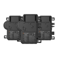
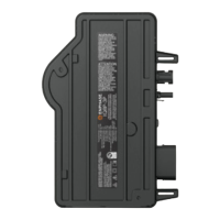
Mount the microinverters
A ) Mount the microinverter horizontally (bracket side up) or vertically.
Always place it under the PV module, protected from direct exposure
to rain, sun, and other harmful weather events. Allow a minimum
of 1.9 cm (3/4”) between the roof and the microinverter. Also, allow
1.3 cm (1/2”) between the back of the PV module and the top of the
microinverter.
3
WARNING: Install the microinverter under the PV module to avoid
direct exposure to rain, UV, and other harmful weather events. Do
not mount the microinverter upside down.
Horizontal mount
B ) For the vertical mount with bifacial PV modules, maintain > 30 cm
(12”) clearance from the edges of the PV module to protect the
microinverter from direct exposure to rain, UV, and other harmful
weather events.
4
C ) Torque the mounting fasteners (1/4” or 5/16”) as follows. Do not
over-torque.
• 6 mm (1/4”) mounting hardware: 5 N m (45 to 50 in-lbs)
• 8 mm (5/16”) mounting hardware: 9 N m (80 to 85 in-lbs)
• When using UL 2703 mounting hardware, use the manufacturer’s
recommended torque value.
D ) Ensure microinverters are mounted with the bracket side up, facing the
solar PV module.
E ) The frame mount bracket allows the microinverter to attach easily and
rapidly to the PV module frame. Use the frame mount bracket in railless
or ballasted solar installations. The frame mount bracket comes in two
sizes, 35 mm (EFM-35MM) and 40 mm (EFM-40MM), depending upon
the thickness (depth) of the PV module frame.
• Place the bracket clamp over the edge of the module frame as
shown in the following image:
• Thread the cap bolt into the threaded insert on the bracket, then
slide the microinverter slot onto the bolt.
Vertical mount
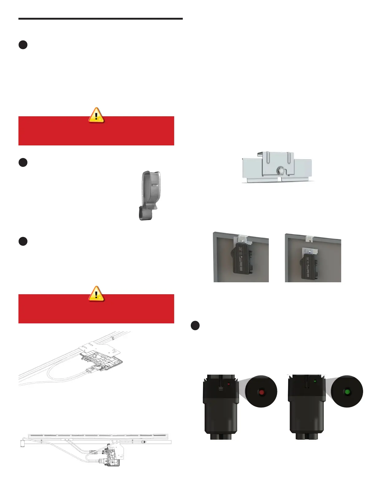
Connect the microinverters
A ) Connect the microinverter to the QD Cable connector. Listen for a click
as the connectors engage.
B ) Ensure that the QD Cable connector is fully seated and locked on the
microinverter AC connector. You can verify the connection using the
green and red indicators on the QD Cable connector as shown in the
following images:
C ) Cover any unused connectors on the AC cable with QD Sealing Caps
(QD-SEAL-10). Listen for a click as the sealing caps engage.
• Slide the microinverter unit onto the bracket clamp. The bolt now
holds the frame mount to the bracket clamp. The microinverter
mounting ange should be on the outside of the module frame as
shown in the following images:
• With a 13 mm or 1/2” socket wrench, tighten the cap screw until
you reach a torque of 18 N m (13 ft).
• When using any racking manufacturer’s MLPE frame mount
bracket, follow the manufacturer’s recommended torque value
and installation guidelines for frame mounting the microinverters.
Improper connection Fully seated and locked
connector
 Loading...