3
E ) Complete the AC connection.
Verify that AC voltage at the site is within range:
Service type and voltage: L1-L2, L2-L3 and L3-L1
208 VAC three-phase 183 to 229 VAC
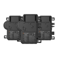
Terminate the unused end of the cable6
WARNING: The terminator cannot be re-used. If you unscrew
the nut, you must discard the terminator.
A ) Remove 20 mm (0.8“) of the cable sheath from the conductors.
B ) Slide the hex nut onto the cable. The grommet inside the terminator
body must remain in place.
C ) Insert the cable into the terminator body so that the four wires land
on separate sides of the internal separator.
D ) To attach the cap:
• Bend the wires down into the recesses of the terminator body
and trim as needed. Place the cap over the terminator body.
• Insert a screwdriver into the slot on the terminator cap to hold
it in place.
• Rotate the hex nut with your hand or a wrench until the latching
mechanism meets the base.
• Do not over-torque.
A
Create an installation map
Create a paper installation map to record microinverter serial numbers
and positions in the array.
A ) Peel the removable serial number label from each microinverter and
afx it to the respective location on the paper installation map.
B ) Peel the label from the IQ Gateway Commercial 2 and afx it to the
installation map.
C ) Always keep a copy of the installation map for your records.
E ) Attach the terminated cable end to the PV racking with a cable clip
or tie wrap so that the cable and terminator do not touch the roof.
To Sheet / A la hoja de: ________
A
B
C
D
E
F
G
H
To Sheet / A la hoja de: ________
To Sheet / A la hoja de: ________
To Sheet / A la hoja de: ________
Panel Group/Grupo de los paneles:
Azimuth/Azimut:
Tilt/Inclinación:
Sheet/Hoja _____ of/de _____
N S E W
N S E O
Installer/Instalador:
Customer/Cliente:
Scan completed map and upload it to Enphase. Click “Add a New System”
at https://enlighten.enphaseenergy.com. Use this map to build the virtual array in Enlighten’s Array Builder.
Escanee el mapa completo y cárguelo en Enphase. Haga clic en “Añadir nuevo sistema”
en https://enlighten.enphaseenergy.com. Utilice este mapa para crear el conjunto de paneles
virtual en el Creador de conjuntos de paneles de Enlighten.
1 2 3 4 5 6 7
Envoy Serial Number Label /
Número de serie de Envoy
8
9
Afx serial
number labels
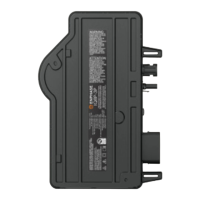
B ) When installing the IQ8 Commercial Microinverter system using QD Cable,
you may have multiple center-tap connectors in the branch circuit. Select
the center-tap connector such that a maximum of nine IQ8 Commercial
Microinverters are installed on either side of the center-tap connector to
limit voltage rise <1% in the QD Cable. Do not exceed branch circuit sizing
mentioned on page 1 in this guide.
C ) Use a Enphase center-tap adapter cable (QD-LINKFW-10) to connect the
center-tapping connector to the extension cable to the PV sub-panel using
a male three-phase Field Wireable QD Connector (QD-CONN-10M).
D ) Use a female three-phase Field Wireable QD Connector (QD-CONN-10F) to
connect the extension cable to the three-pole 20 A over-current protection
device (OCPD) in the PV sub-panel.
WARNING: The center-tapping AC male connector is marked
“Center tap; Not for microinverter connection”. Do not use the center
tap connectors for connecting to the microinverter.
7
Provide an AC connection to the branch circuit
Center-feeding the branch circuit
Enphase recommends that the total percentage of voltage rise in the AC
wiring be a maximum of 2%, with (an inclusive) less than 1% voltage rise in the
QD Cable.
Although the QD Cable is optimized for minimal VRise, it is still important to
calculate the total VRise for the entire system for the farthest microinverter in
the branch circuits from the point of common coupling.
As voltage rise is exponential, reducing the number of microinverters in the
branch circuit signicantly reduces the voltage measured at the farthest
microinverter in the branch. One way to minimize this voltage rise is to
center-feed the branch, that is, divide the circuit into two sub-branch circuits
protected by a single OCPD. Hence, for all installations with IQ8 Commercial
Microinverters, center-feeding of a three-phase AC supply is recommended.
Follow these installation steps for center-feeding the microinverter branch
circuits.
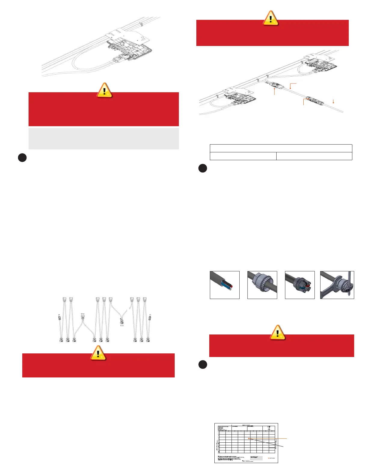
A ) All three QD Cable SKUs include center-tapping connectors after every
six AC male QD Cable connectors in the QD Cable spool. The center-tap
connectors are sealed with sealing caps and the sealing cap should be
removed only when the connector is used for feeding the AC supply to the
branch.
5
To remove a sealing cap or AC connector, you must use an QD
Disconnect Tool.
WARNING: Install sealing caps on all unused AC connectors as
these connectors become live when the system is energized.
Sealing caps are required for protection against moisture ingress.
B C D
WARNING: Do not remove pre-installed sealing caps on the
center-tap connector, if the connector is not used for center-
feeding AC supply.
Extension cable
to PV subpanel
Female three-phase Field Wireable QD
Connector (QD-CONN-10F)
Center tapping adapter
cable QD-LINKFW-10
Center Tap Connector;
NOT for MICROINVERTERS
 Loading...