4
ACTIVATE MONITORING AND CONTROLS
After you have installed the microinverters, follow the procedures in the IQ
Gateway Commercial 2 Quick Install Guide to activate system monitoring,
set up grid management functions, and complete the installation.
•
Connecting the IQ Gateway Commercial 2 and detecting devices.
•
Connecting to the Enphase Installer App, registering the system, and
building the virtual array.
NOTE: Installers may see numerous ACVOOR (AC voltage out of range)
events during the commissioning of IQ8 Commercial systems if the grid
has higher impedance or operating in a region with wide voltage/frequency
regulation.
Energize the system
A ) Turn ON the AC disconnect or circuit breaker for the branch circuit.
B ) Turn ON the main utility-grid AC circuit breaker. Your system will start
producing power after a ve-minute wait time.
C ) Check the LED on the connector side of the microinverter:
LED Indicates
Flashing
green
Normal operation. AC grid function is normal, and there is communica-
tion with the IQ Gateway Commercial 2.
Flashing
orange
The AC grid is normal, but there is no communication with the IQ Gateway
Commercial 2.
Flashing red The AC grid is either not present or not within specication.
Solid red There is an active “DC Resistance Low, Power Off” condition. To reset,
refer to the Commercial PV Design Guide IQ8 Commercial Microinverter
System Section DC Resistance Low – Power Off Condition at: https://
enphase.com/installers/resources/documentation.
Rapid red/
Flashing
orange
IQ8 Commercial Microinverter has detected a PV panel that is operating
outside the the arc-safe region.
Enphase connector rating: Enphase connectors on the assemblies in
the following table have a maximum current of 20 A, a maximum OCPD
of 20 A, and maximum ambient temperature of -40° to 79°C (-40° to
174.2°F). Never disconnect any connectors under load.
Part number Model Maximum voltage
840-01922
QD-12-13-120
250 VAC
840-01923
QD-12-20-120
250 VAC
840-01924
QD-12-25-108
250 VAC
860-00776 ECA-EN4-S22-12 119 VDC
860-00792 ECA-EN4-S22-10-12 119 VDC
860-01831 ECA-EN4-S22-10-12 119 VDC
9
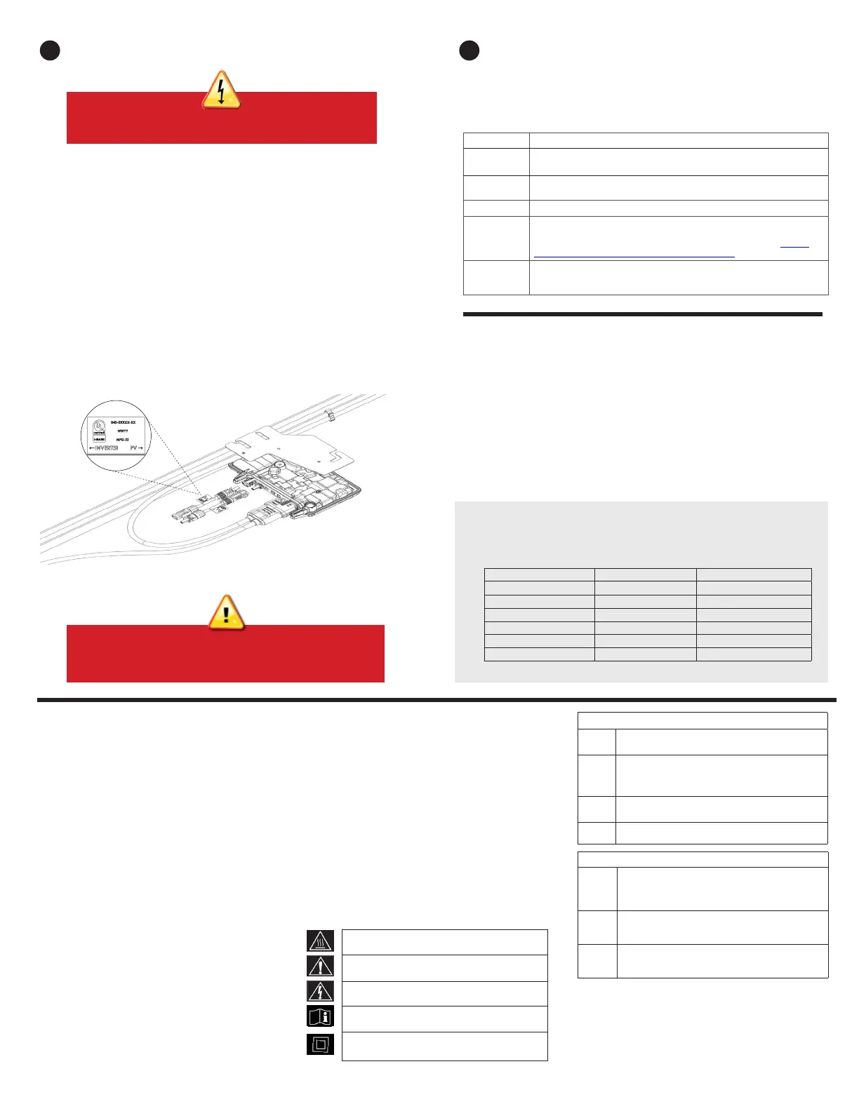
Connect the PV modules to the microinverter
A ) IQ8 Commercial Microinverter has an EN4 bulkhead for DC connection
and bulkhead adapter cable for EN4 to MC4 connection. If your PV
modules have TE PV4S SOLARLOK connectors, you may plug them
directly into the IQ8 Commercial Microinverter with EN4 bulkhead. Or
use the adapter cable for PV modules with MC4 connectors. If your
PV module has any other connector, use the EN4 to non-terminated
adapter cable.
When using adapters, make sure they are fully seated. Do not reverse
the adapter connections. When using an adapter cable, ensure that
EN4 (TE PV4S SOLARLOK) connectors are used for connection
with the microinverter. Refer to the label on the adapter cables.
IQ8 Commercial Series Microinverter bulkhead and adapter male and
female DC connectors must only be mated with the identical type and
manufacturer brand of male/female connector.
B ) Check the LED on the connector side of the microinverter. The LED
ashes six times when DC power is applied.
DANGER! Electric shock hazard. The DC conductors of
this PV system are ungrounded and may be energized.
8
WARNING: If adapters are used, ensure they are installed
in the correct orientation. Refer to label on the adapter
cables for correct connection.
PV rapid shutdown equipment
(PVRSE)
This product is UL Listed as PV rapid shutdown
equipment and conforms with NEC-2014, NEC-2017,
NEC-2020, section 690.12 and C22.1-2015 Rule 64-218
rapid shutdown of PV Systems for AC and DC conductors
when installed according to the following requirements:
• Microinverters and all DC connections must be
installed inside the array boundary. Enphase further
requires that the microinverters and DC connections
be installed under the PV module to avoid direct
exposure to rain, UV, and other harmful weather
events.
• The array boundary is dened as 305 mm (1 ft) from
the array in all directions, or 1m (3 ft) from the point of
entry inside a building.
This rapid shutdown system must be provided with
an initiating device and (or with) a status indicator,
which must be installed in a location accessible to rst
responders or be connected to an automatic system that
initiates rapid shutdown upon the activation of a system
disconnect or activation of another type of emergency
system. The initiator shall be listed and identied as a
disconnecting means that plainly indicates whether it is in
the “off” or “on” position. Examples are:
• Service disconnecting means
• PV system disconnecting means
• Readily accessible switch that indicates whether it is in
the “off” or “on” position
The handle position of an AC disconnect switch or circuit
breaker can be used as an indicator based on regulations
dened by the Authority Having Jurisdiction (AHJ) in
SAFETY
IMPORTANT SAFETY INSTRUCTIONS
SAVE THIS INFORMATION. This guide
contains important instructions to follow during the
installation of the IQ8P-3P and IQ8H-3P Microinverters.
WARNING: Hot surface.
WARNING: Refer to safety instructions.
DANGER: Risk of electric shock.
Refer to manual
Double-Insulated
General safety
+
DANGER: Risk of electric shock. Do not use Enphase
equipment in a manner not specied by the manufac-
turer. Doing so may cause death or injury to persons, or
damage to equipment.
+
DANGER: Risk of electric shock. Be aware that installation
of this equipment includes risk of electric shock.
+
DANGER: Risk of electric shock. The DC conductors of
this photovoltaic system are ungrounded and may be
energized.
Safety symbols
+
DANGER: Indicates a hazardous situation, which if not
avoided, will result in death or serious injury.
*
WARNING: Indicates a situation where failure to follow
instructions may be a safety hazard or cause equipment
malfunction. Use extreme caution and follow instructions
carefully.
;
WARNING: Indicates a situation where failure to follow
instructions may result in burn injury.
✓
NOTE: Indicates information particularly important for
optimal system operation.
the region. Refer to NEC or CSA C22.1-2018 for more
information. Additionally, in a prominent location near the
initiator device, a placard or label must be provided with a
permanent marking including the following wording:
’PHOTOVOLTAIC SYSTEM EQUIPPED WITH RAPID
SHUTDOWN’ The term ‘PHOTOVOLTAIC’ may be replaced
with ‘PV.’ The placard, label, or directory shall be reective,
with all letters capitalized and having a minimum height of
9.5 mm (3/8”) in white on a red background.
 Loading...