L200/L201/L100/L101 Revision A
Confidential
Disassembly/Assembly Disassembling/Assembling Flowchart 18
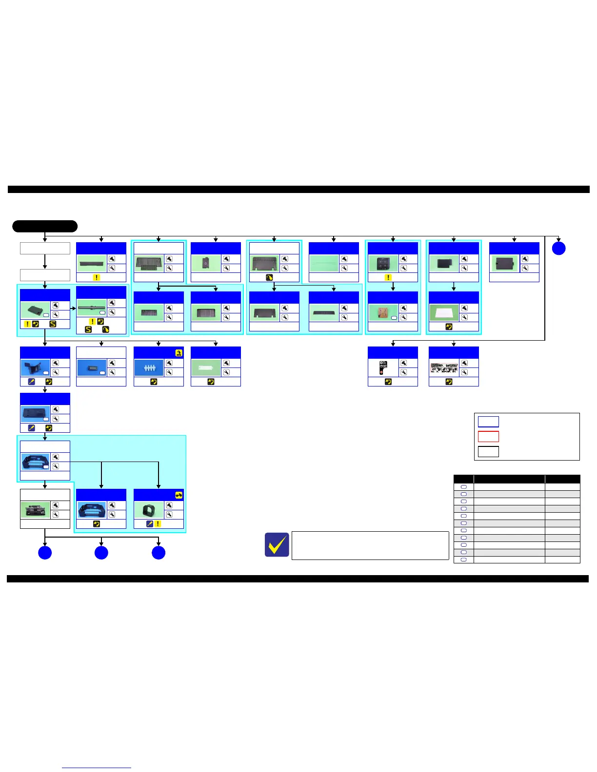
1.2.2 Disassembling/Reassembling Flowchart
1.2.2.1 Housing Part
Flowchart 1-1. Disassembling Flowchart of Housing Part (1)
L200/L201 START
A
Ink Cartridge
Cover
---
2
---
Panel Unit
ASF Cover
---
2
---
Jam Cover
---
2
(p 25)
Screw type/torque list
Symbol Screw type Torque
C.B.P-TITE SCREW 3x8 5.0 ± 0.5 kgf·cm
C.B.P-TITE SCREW 3x10 5.0 ± 0.5 kgf·cm
C.B.S-TITE SCREW 3x5 7.5
± 0.5 kgf·cm
C.B.P-TITE SCREW 2.6x8 4.0 ± 0.25 kgf·cm
C.P.(P1) SCREW 2.6x3.5 3.5
± 0.25 kgf·cm
C.B.S-TITE SCREW 2x5 3.5 ± 0.25 kgf·cm
C.B.P-TITE SCREW 2x6 3.0
± 0.25 kgf·cm
C.F.B-TITE SCREW 2.6x6 3.0 ± 0.25 kgf·cm
C.B.P TITE SCREW 2.5x5 5.0 ~ 6.0 kgf·cm
C.B.P TITE SCREW 3x6 5.0 ~ 6.0 kgf·cm
C.B.P TITE SCREW 2.6x16 5.0 ~ 6.0 kgf·cm
S1
S2
S3
S4
S5
S6
S7
S8
S9
S10
S11
Jam Cover
Middle
Housing
---
---
(p 29)
Panel Unit
---
4
(p 23)
Panel Board
1
---
---
S1
Document Cover
---
2
---
Document Pad
---
---
(p 23)
Tray Exit Ou ter
---
2
---
Tray Exit Inner
---
2
---
Paper Support
Tray
---
2
---
Paper Support
Tray 2
---
2
---
Middle Housing
Assy
4
4
---
S2
Printer
Mechanism
---
---
---
B
(p 21)(p 20)
CIS
4
---
(p 23)
(p 31) (p 39)
S2
Scanner Unit
4
4
(p 23) (p 31)
S2
Stacker Assy
---
2
---
Paper Support
Assy
---
2
(p 39)
L200/L201 specific parts/unit
L100/L101 specific parts/unit
Ink Supply
Holder Assy
2
2
(p 29) (p 29)
S10
C
(p 22)
Ink Tube Guide
1st
1
2
(p 29) (p 27)
S9
Tube Pressing
Plate
1
---
---
S9
Joint
---
2
(p 28)
USB Cover
---
2
(p 25)
Rear Cover
---
1
---
D
(p 19)
Valv e Po siti o n
Label
---
---
(p 29)
Refilling Ink
Label
---
---
(p 29)
Tube Guide Plate
Support
---
---
(p 29)
See “ Flowchart 1-2 Disassembling Flowchart of Housing Part (2)
(p19)” for disassembly of the Housing Part of L100/L101.
Common parts/unit
 Loading...