L200/L201/L100/L101 Revision A
Disassembly/Assembly Details of Disassembling/Reassembling by Parts/Unit 23
Confidential
1.3 Details of Disassembling/Reassembling by Parts/Unit
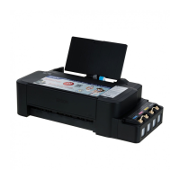
Panel Unit (L200/L201)
Do not lift the Panel Unit too fast, since the Panel FFC is connected
to the back of the Panel Unit.
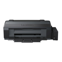
Document Pad (L200/L201)
When installing the Document Pad, follow the procedure below.
1. Place the Document Pad with the side where the double-sided
tape attached upward on the document glass aligning its corner
with the origin position.
2. Close the Document Cover to attach the Document Pad.
Standard line
Double-sided tape
Document Cover
Document Pad
Origin Position
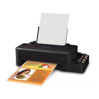
Scanner Unit (L200/L201)
Do not lift the Scanner Unit too fast, since the Panel FFC, Scanner Motor cable and Scanner FFC are connected to the rear side of the Scanner Unit.
Tighten the screws in the order indicated in the figure above.
Panel FFC
Scanner FFC
Scanner Motor cable
Scanner
Unit
Scanner Unit
1
2
4
C.B.P-TITE SCREW 3x10 (5.0 ± 0.5 kgf·cm)
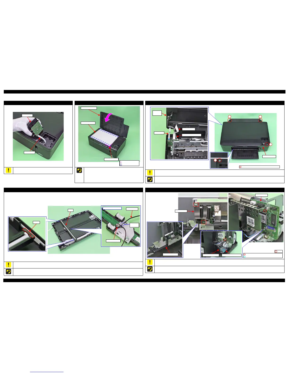
CIS (L200/L201)
Be careful not to lose the Spacer because it comes off easily when disassembling the CIS.
When installing the spacers, be sure to place them with the cutout facing inward.
Align the toothed side of the Timing Belt with the same shaped rib of the backside of the CIS, and secure the Timing Belt with Torsion Spring.
Backside of the CIS
Timing Belt
Torsion Spring
Toothed
side
Main Board
Take care not to damage the PE Sensor Lever.
Align the ribs (x3) of the Main Frame with the cutouts of the Main Board.
Screw one side of the grounding wire (w/ ferrite core) together with the plate of the PF Motor, and the other side together with the Main Board.
C.B.S-TITE SCREW 3x5 (7.5 ± 0.5 kgf·cm)
C.B.P-TITE SCREW 3x8 (5.0 ± 0.5 kgf·cm)
Grounding wire Plate of PF Motor
 Loading...