EVCO S.p.A. | EV3411M | Instruction sheet ver. 1.0 | Code 1043411ME103 | Page 2 of 2 | PT 46/17
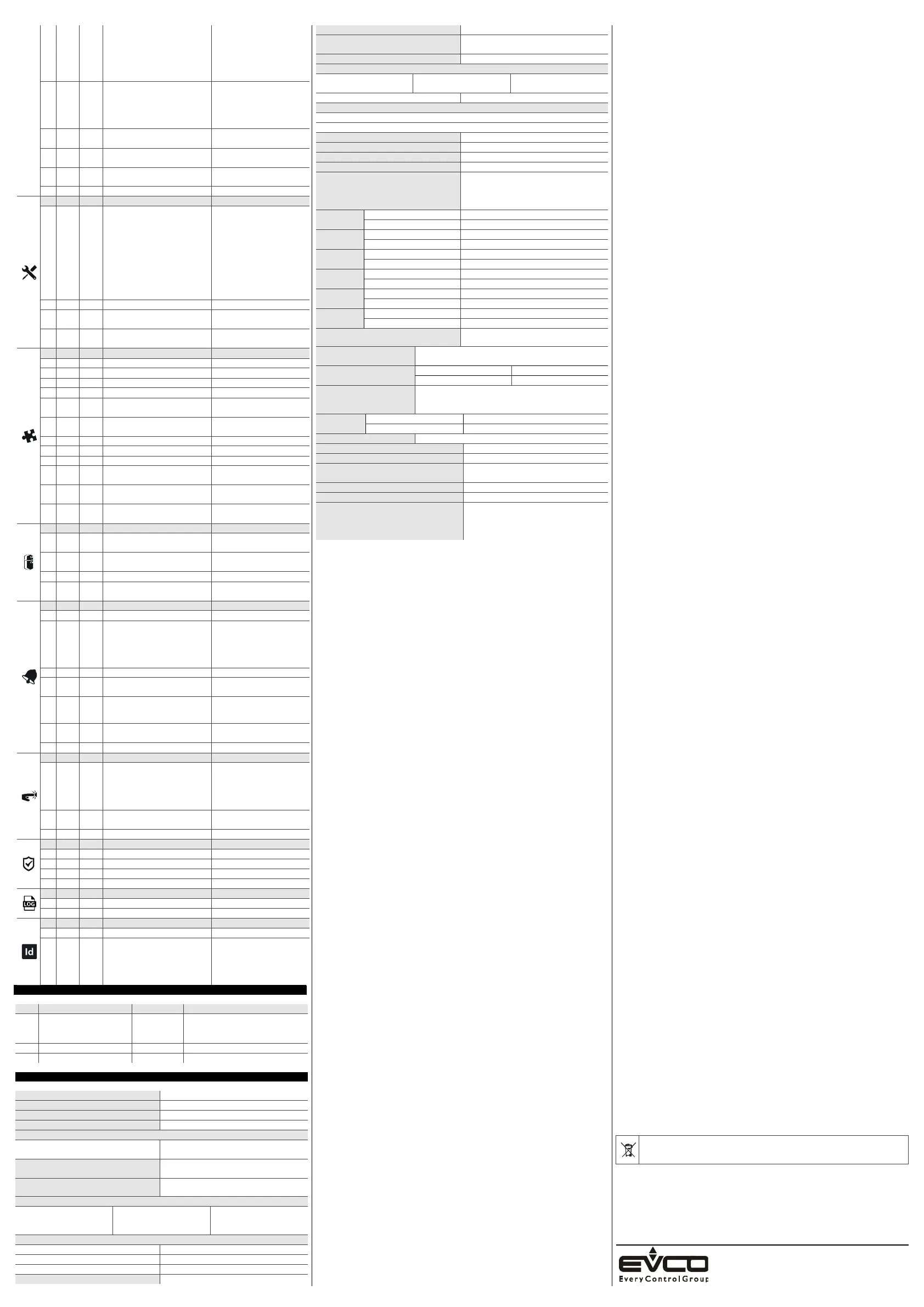
4
P1
0
enable decimal point °C
0 = no 1 = yes
if P0 = 2 or 3, not effective
if P0 = 8... 11, position of
decimal point:
0 = none
1 = tens digit
5
P2
0
measurement unit
0 = °C 1 = °F
2 = % 3 = bar
4 = none
options 2… 4 effective only on
LEDs and if P0 = 8… 11
6
P3
0.0
minimum transducer calibration
value
-199... 999 points
7
P4
100
maximum transducer calibration
value
-199... 999 points
8
P5
0
value displayed
0 = regulation temperature
1 = setpoint
9 P8 5 display refresh time
0... 250 s : 10
N. PAR. DEF. DIGITAL OUTPUTS
MIN... MAX.
10
uA
0
outputs configuration
0 = analog output not
enabled, K1 relay with
regulator
1 = analog output
proportional to the
regulation temperature,
K1 relay not enabled
2 = analog outputwith
regulator, K1 relay not
enabled
11 ub 0 type of analogue output
0 = 0-10 V 1 = PWM
12
uc
0.0
regulation temperature for
minimum analogue output value
-199... ud °C/°F/points
13
ud
100
regulation temperature for
maximum analogue output value
uc... 199 °C/°F/points
N. PAR. DEF. REGULATION
MIN... MAX.
14
rA 0 PID control configuration 0 = off 1 = on
15
r0 2.0 setpoint differential 1... 99 °C/°F
16
r1 0.0 minimum setpoint
-199 °C/°F... r2
17
r2 350 maximum setpoint
r1... 999 °C/°F
18
r5
0
hot or cold mode regulation
regulator
0 = cold mode
1 = hot mode
19
r11
0.0
digital input second setpoint
-199... 999 °C/°F
setpoint + r11
20
r14 50 proportional band
1... 999 °C/°F
21
r15 60 integral action time
0... 999 s
22
r16 30 derivative action time
0... 999 s
23
r17
180
PID regulator cycle time on PWM
relay or analogue output
1... 999 s
24
r18
0
PID regulator minimum time on
on PWM relay or analogue output
0... 240 s
25
r19
0
PID regulator minimum time off
on PWM relay or analogue output
0... 240 s
N. PAR. DEF. REGULATOR PROTECTION
MIN... MAX.
26
C1
0
minimum time between two
power-ons of regulator
0... 240 min
27
C2
0
minimum time off and delay from
power-on of regulator
0... 240 min
28
C3 0 minimum time on regulator
0... 240 s
29
C4
0
regulator activity during
regulation probe alarm
0 = off 1 = on
N. PAR. DEF. ALARMS
MIN... MAX.
30
A1 0.0 temperature alarm threshold
-199... 999 °C/°F
31
A2
0
temperature alarm type
0 = disabled
1 = absolute minimum
2 = absolute maximum
3 = minimum relative to SP
4 = maximum relative to SP
32
A3 0 temperature alarm delay
0... 999 min
33
A7
0
temperature alarm delay after
modifying setpoint and power-on
0... 999 min
34
A8
0
additional alarm signal delay
after silencing if the condition
persists
0... 999 min
35
A11
2.0
temperature alarm switch off
differential
1... 99 °C/°F
36
A13 1 enable alarm buzzer
0 = no 1 = yes
N. PAR. DEF. DIGITAL INPUTS
MIN... MAX.
37
i5
0
multi-purpose input function
0 = disabled
1 = alarm iA
2 = alarm iA + regulator off
3 =
switches device on/off
4 = modifies setpoint
38
i6
0
multi-purpose input activation
0 = with contact closed
1 = with contact open
39
i7 0 multi-purpose input alarm delay
0... 999 s
N. PAR. DEF. SECURITY
MIN... MAX.
40
POF 1 enable ON/STAND-BY key
0 = no 1 = yes
41
PAS -19 password -99... 999
42
PA1 426 1
st
level password
-99... 999
43
PA2 824 2
nd
level password
-99... 999
N. PAR. DEF. EVLINK DATA-LOGGING
MIN... MAX.
44
bLE 1 activate Bluetooth
0 = no 1 = yes
45
rE0 15 datalogger sampling interval
0... 240 min
N. PAR. DEF. MODBUS MIN... MAX.
46
LA 247 MODBUS address
1... 247
47
Lb
3
MODBUS baud rate
0 = 2,400 baud
1 = 4,800 baud
2 = 9,600 baud
3 = 19,200 baud
even
9 ALARMS
COD. DESCRIPTION
RESET
TO CORRECT
Pr1
regulation probe alarm
automatic
- check P0
- check probe integrity
- check electrical connection
AL
temperature alarm
automatic
check A1, A2 and A3
iA multi-purpose input alarm
automatic check i5 and i6
10 TECHNICAL SPECIFICATIONS
Purpose of the control device
Function controller
Construction of the control device
Built-in electronic device
Container
Black, self-extinguishing
Category of heat and fire resistance
D
Measurements
75.0 x 33.0 x 59.0 mm (2 15/16 x 1 5/16 x
2 5/16 in) with fixed screw terminal blocks
75.0 x 33.0 x 81.5 mm (2 15/16 x 1 5/16 x
3 3/16 in) with plug-in screw terminal blocks
Mounting methods for the control device
To be fitted to a panel, snap-in brackets
provided
Degree of protection provided by the
covering
IP65 (front)
Connection method
Fixed screw terminal blocks
for wires up to 2.5 mm²
Plug-in screw terminal blocks
for wires up to 2.5 mm² (on
request)
Pico-Blade connector
Maximum permitted length for connection cables
Power supply: 10 m (32.8 ft)
Analogue inputs: 10 m (32.8 ft)
Digital inputs: 10 m (32.8 ft)
Analogue outputs 0-10 V: 10 m (32.8 ft)
PWM analogue outputs: 1 m (3.28 ft)
Digital outputs: 10 m (32.8 ft)
Operating temperature
From -5 to 55 °C (from 23 to 131 °F)
Storage temperature
From -25 to 70 °C (from -13 to 158 °F)
Operating humidity
Relative humidity without condensate from 10
to 90%
Pollution status of the control device
2
Compliance:
RoHS 2011/65/EC
WEEE 2012/19/EU
REACH (EC) Regulation
1907/2006
EMC 2014/30/EU
LVD 2014/35/EU
Power supply:
230 VAC (+10 % -15 %), 50/60 Hz (±3 Hz), max. 4 VA in EV3... M7
12-24 VAC/DC (+10% -15%), 50/60 Hz (±3 Hz), max. 5 VA/3W in EV3... M3
Earthing methods for the control device
None
Rated impulse-withstand voltage
4 KV
Over-voltage category
4 KV in EV3... M7; 330 V in EV3... M3
Software class and structure
III in EV3... M7; I in EV3... M3
Analogue inputs
1 for PTC, NTC, Pt 100, Pt 1000 or Ni 120
probes, J or K thermocouples, 0-20 mA, 4-20
mA, 0-10 V or 2-10 V transducers (regulation
probe)
PTC probes
Measurement field:
from -50 to 150
(from -58 to 302 °F)
Resolution:
0.1 °C (1 °F)
NTC probes
Measurement field:
from -40 to 110 °C (from -58 to 230 °F)
Resolution:
0.1 °C (1 °F)
Pt 100 and Pt
1000 probes
Measurement field:
from -100 to 650
(from -148 to 999 °F)
Resolution:
0.1 °C (1 °F)
Ni 120 probes
Measurement field:
from -80 to 300 °C (from -112 to 999 °F)
Resolution:
0.1 °C (1 °F)
J thermo-
couples
Measurement field:
from 0 to 700 °C (from 32 to 999 °F)
Resolution:
1 °C (1 °F)
K thermo-
couples
Measurement field:
from 0 to 999 °C (from 32 to 999 °F)
Resolution:
1 °C (1 °F)
0-20 mA, 4-20 mA, 0-10 V and 2-10 V
transducers:
can be configured
Digital inputs
1 dry contact (multi-purpose), not available if the analogue
input is configured for Pt 100, Pt 1000 or NI 120 3 wires
Dry contact
Contact type:
3.3 V, 1 mA
Protection:
none
Analogue outputs
1 for 0-10 V or PWM signal.
Available in the models with power supply 12-24 VAC/DC on
condition that they are powered at 24 VAC/DC
Signal
0-10 V
Minimum applicable impedance
1 KOhm; 2 KOhm in EV3... M7.
Resolution:
0.01 V
Digital outputs
1 with electromechanical relay (K1 relay)
K1 relay
SPST, 16 A res. @ 250 VAC
Type 1 or Type 2 Actions
Type 1
Additional features of Type 1 or Type 2
actions
C
Displays
LED display, 3 digit, with function icons
Alarm buzzer
Built-in
Communications ports
1 TTL MODBUS slave port for programming
key, for EVlink Wi-Fi module (EpoCA
system), for EVlink BLE module (app
EVconnect) or for serial interface (BMS)
N.B.
The device must be disposed of according to local regulations governing the collection
of electrical and electronic equipment.
This document and the solutions contained therein are the intellectual property of EVCO and thus
protected by the Italian Intellectual Property Rights Code (CPI). EVCO imposes an absolute ban on the
full or partial reproduction and disclosure of the content other than with the express approval of EVCO.
The customer (manufacturer, installer or end-user) assumes all responsibility for the configuration of the
device.
EVCO accepts no liability for any possible errors in this document and reserves the right to make any
changes, at any time without prejudice to the essential functional and safety features of the equipment.
EVCO S.p.A.
Via Feltre 81, 32036 Sedico (BL) ITALY
telefono 0437 8422 | fax 0437 83648
email info@evco.it | web www.evco.it
 Loading...