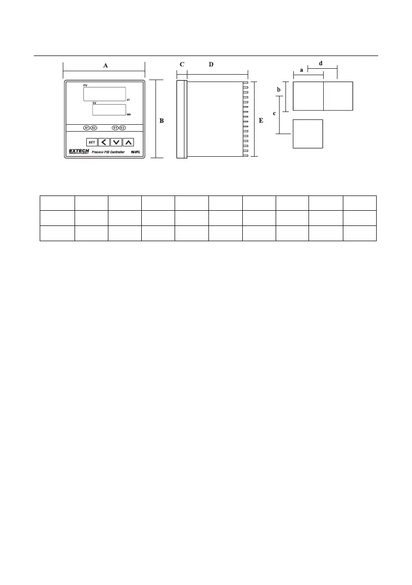
3. Panel Cut-out, Dimensions, and Mounting
FIGURE 3.1: VFL CUT-OUT AND DIMENSIONS
Units: mm (columns ‘a’ and ‘b’ are +/- 0.5mm)
3.1 48VFL Mounting
1. Remove the plastic mounting bracket and slide the controller into the panel, through the
cutout.
2. Replace the mounting bracket and tighten the bracket screws. Do not over tighten.
3. Do not obstruct the ventilation openings on the side of the controller.
3.2 96VFL Mounting
1. The 96VFL uses two metal brackets (supplied) affixed to the top and bottom of the
controller to secure it to the panel.
2. Slide the controller into the panel and connect the bracket clips to the insert holes on the
top and bottom of the controller.
3. Tighten the bracket screws to secure the controller in the panel. Do not overtighten.
 Loading...