Operation Overview
The CT70 AC Circuit Load Tester can test outlets or circuits under load for proper wiring, reverse
polarity, and the presence of a ground. The CT70 uses a simple menu-driven display to allow the
user to quickly see line voltage, voltage drop under full load, ground-to-neutral voltage, and line
impedance. The GFCI testing utility is performed separately per UL-1436, disrupting the flow of
electricity if a functioning GFCI is present.
Note: To avoid the buildup of heat during load testing, allow at least 20 seconds to elapse between
tests. In addition to the safety benefits, this will allow the meter to maintain its stated accuracy
during repeated tests.
Warning: To avoid damage to the instrument, do not use this device on the output of a UPS
system, a light dimmer, or a square wave generator.
Warning: Use only the supplied power/test cord (CT70-AC) with this equipment
Interpreting Measurement Results
Important note: The CT70 is a microprocessor controlled device that prioritizes its tasks. Taking a
reading and analyzing the results are its top priorities. This is why, at times, the keypad may not
respond immediately. The internal computer places a higher priority on completing a test than on
recognizing a keystroke. To minimize this effect, press and hold a key until the display menu
changes.
In addition to the main Wiring Configuration icon, shown on the meter display, the measurement
modes are accessed using the four (4) menu items shown on the left side of the display. The menu
items are:
1. Voltage (V)
2. Voltage drop (Vd)
3. ASCC (Available short circuit current)
4. Impedance (Z)
Use the ▼ button to scroll the menu list.
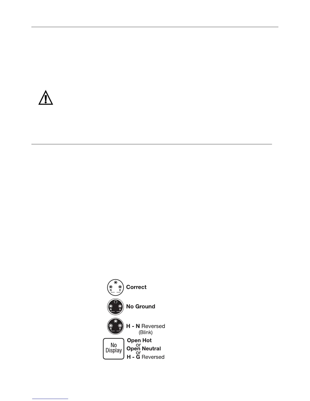
The wiring configuration screen shows correct wiring, reverse polarity wiring, and ‘no ground’
conditions. The three circles on the wiring configuration icon indicate the wiring status. The circles
are coded, changing appearance (clear, solid, and flashing) to indicate the measurement results. A
table is provided below for interpreting the circle code.
Blue Display
Red Display
Red Display
Blank Display
 Loading...