Testing Procedures
Test 1: Wiring Verification
The wiring configuration is the first test result that is displayed. Refer to the table presented earlier in
the user guide for the test result key.
For wiring conditions other than normal, the CT70 is limited in the type of tests it can perform on a
circuit until the circuit’s wiring issues are resolved. For ‘no ground’ conditions, only the line voltage
and voltage drop tests can be made. For reverse polarity conditions, open neutral, or open hot
conditions the meter will not display since power will not be available.
Notes:
• The meter cannot sense two hot wires in a circuit
• The meter cannot display the results of more than one circuit issue at time
• The meter cannot sense ground reversals
Test 2: Voltage Measurements
Warning: Do not take measurements on circuits with voltages higher than 300VAC
(maximum voltage rating).
Line voltage measurements should be 120VAC ±10% at 60Hz. For noise-free sine waves, the peak
voltage should be 1.414 times the rms line voltage reading. Ground to neutral voltage should be less
than 2 VAC in which case the display backlight will appear blue in color, if ground to neutral voltage
is greater than 2 VAC the backlighting appears in red.
Higher ground to neutral voltages indicates excessive current leakage between the neutral and
ground conductors. Excessive ground to neutral voltage may result in inconsistent or intermittent
equipment performance.
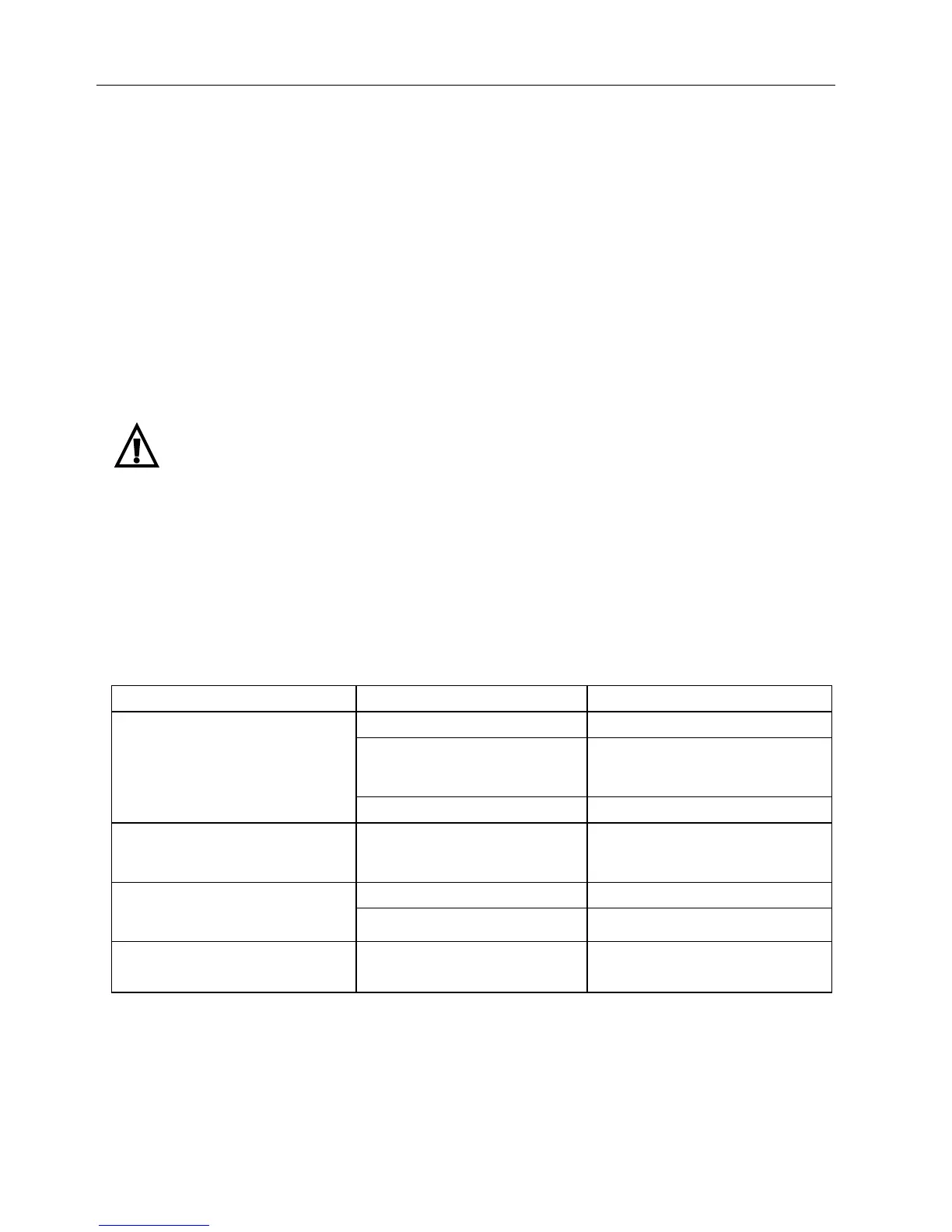
Voltage Measurement Troubleshooting Suggestions
Problems Likely Causes Possible Solutions
Overloaded circuit Redistribute loads
Connection within circuit or at
the panel has excessive
resistance
Repair high resistance connection
Out of tolerance Line Voltage
(Line should be 120V±10%)
Utility company problem Contact the power utility company
High Ground to Neutral voltage
(Readings > 2VAC indicated a
problem)
Neutral to Ground current
leakage
Identify leakage, check for multiple
bonding points
Supply voltage out of tolerance Contact power utility company Peak Voltage out of tolerance (For
120V Line, Peak should measure
between 153 - 183V)
High peak loads on circuit Redistribute electronic devices
Frequency out of tolerance
(50/60Hz)
Supply frequency out of
tolerance
Contact power utility company
 Loading...